
User manual


Rev. 1.00, 05/04, page 468 of 544
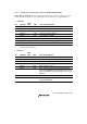
20.2 Mode Transitions and LSI States
Figure 20.1 shows the enabled mode transition diagram. The mode transition from program
execution state to program halt state is performed by the SLEEP instruction. The mode transition
from program halt state to program execution state is performed by an interrupt. The STBY input
causes a mode transition from any state to hardware standby mode. The RES input causes a mode
transition from a state other than hardware standby mode to the reset state. Table 20.2 shows the
LSI internal states in each operating mode.
Program halt state
Program execution state
SCK2 to
SCK0 are
0
SCK2 to
SCK0 are
not 0
SLEEP instruction
SSBY = 1, PSS = 1,
DTON = 1, LSON = 1
Clock switching
exception handling
SLEEP instruction
SSBY = 1, PSS = 1,
DTON = 1, LSON = 0
After the oscillation
stabilization time
(STS2 to STS0), clock
switching exception
handling
SLEEP instruction
SLEEP
instruction
External
interrupt *
3
Any interrupt
SLEEP
instruction
SLEEP
instruction
SLEEP instruction
Interrupt *
1
LSON bit = 0
Interrupt *
2
Interrupt *
1
LSON bit = 1
STBY pin = High
RES pin = Low
STBY pin = Low
SSBY = 0, LSON = 0
SSBY = 1,
PSS = 0, LSON = 0
SSBY = 0,
PSS = 1, LSON = 1
SSBY = 1,
PSS = 1, DTON = 0
RES pin = High
: Transition after exception processing : Power-down mode
Reset state
High-speed mode
(main clock)
Medium-speed
mode
(main clock)
Subactive mode
(subclock)
Subsleep mode
(subclock)
Hardware
standby mode
Software
standby mode
Sleep mode
(main clock)
Watch mode
(subclock)
Notes:
1.
2.
3.
NMI, IRQ0 to IRQ2, IRQ6, IRQ7, and WDT1 interrupts
NMI, IRQ0 to IRQ7, WDT0, WDT1, TMR0, and TMR1 interrupts
NMI, IRQ0 to IRQ2, IRQ6, and IRQ7 interrupts
• When a transition is made between modes by means of an interrupt, the transition cannot be made
on interrupt source generation alone. Ensure that interrupt handling is performed after accepting the
interrupt request.
• Always select high-speed mode before making a transition to watch mode or sub-active mode.
Figure 20.1 Mode Transition Diagram