
User manual


Rev. 1.00, 05/04, page 537 of 544
Appendix
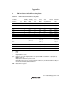
A. I/O Port States in Each Processing State
Table A.1 I/O Port States in Each Processing State
Port Name
Pin Name
Reset
Hardware
Standby
Mode
Software
Standby
Mode
Watch
Mode
Sleep
Mode
Sub-
sleep Mode
Subactive
Mode
Program
Execution
State
Port 1 T T kept kept kept kept I/O port I/O port
Port 2 T T kept kept kept kept I/O port I/O port
Port 3 T T kept kept kept kept I/O port I/O port
Port 4 T T kept kept kept kept I/O port I/O port
Port 5 T T kept kept kept kept I/O port I/O port
Port 6 T T kept kept kept kept I/O port I/O port
Port 7 T T T T T T Input port Input port
Port 8 T T kept kept kept kept I/O port I/O port
Port 97 T T kept kept kept kept I/O port I/O port
Port 96
φ
EXCL
T T [DDR = 1] H
[DDR = 0] T
EXCL input [DDR = 1]
clock output
[DDR = 0] T
EXCL input EXCL input Clock output/
EXCL input/
input port
Ports 95 to 90
T T kept kept kept kept I/O port I/O port
Port A T T kept kept kept kept I/O port I/O port
Port B T T kept kept kept kept I/O port I/O port
Ports C to G T T kept kept kept kept I/O port I/O port
[Legend]
H: High
L: Low
T: High-impedance state
kept: Input ports are in the high-impedance state (when DDR = 0 and PCR = 1, input pull-up
MOSs remain on).
Output ports maintain their previous state.
Depending on the pins, the on-chip peripheral modules may be initialized and the I/O port
function determined by DDR and DR used.
DDR: Data direction register