
User manual


RSKR8CLA8A 2. Power Supply
2. Power Supply
2.1 Requirements
This RSK is supplied with an E8a debugger. The debugger is able to power the RSK board with up to 300mA.
When the RSK is connected to another system then that system should supply power to the RSK. All RSK and
RSK+ boards have an optional centre positive supply connector using a 2.0mm barrel power jack.
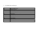
This RSK supports 5V and 3.3V inputs, and requires specific configuration for different inputs. Details of the
external power supply connections are shown in Table 2-1 below.
Connector Supply Voltages R30 Setting R31 Setting
Regulated, 5V DC Fitted Removed PWR1
Regulated, 3.3V DC Removed Fitted
Table 2-1: Main Power Supply Requirements
The RSK board is neither under nor over voltage protected. Use a centre positive regulated supply for this board.
2.2 Power-Up Behaviour
When the RSK is purchased, the RSK board has the ‘Release’ or stand-alone code from the example tutorial code
pre-programmed into the Renesas microcontroller. On powering up the board the user LEDs will start to flash.
After 200 flashes or after pressing any switch, the LEDs will flash at a rate controlled by the potentiometer.
R20UT0284EG0101 Rev. 1.01 Page 8 of 34
Jun 16, 2011