SmartBook for Renesas R8C/Tiny Microcontrollers SmartBook for Renesas R8C/Tiny Microcontrollers R 8C /Ti www.MightyMicons.
SmartBook for Renesas R8C/Tiny Microcontrollers SmartBook for Renesas R8C/Tiny Microcontrollers www.MightyMicons.
SmartBook for Renesas R8C/Tiny Microcontrollers www.MightyMicons.com Phone : 0091 427 2449238 / 3209844 Fax : 0091 427 2431312 Email : feplslm@frontlinemail.com Dear Reader, Thanks for taking your time to read this SmartBook on Renesas R8C/Tiny Microcontrollers. As you know well, we have been associated with this R8C/Tiny series since its introduction into the market and we introduced many hardware and software tools to support this micon family.
SmartBook for Renesas R8C/Tiny Microcontrollers Contents Chapter 1 R8C/Tiny Architecture 1.1 Introduction ............................................................................................................... 1 1.2 R8C/Tiny Family ....................................................................................................... 3 1.3 Overview of R8C/Tiny Family .................................................................................. 4 1.4 R8C/Tiny Architecture .............
SmartBook for Renesas R8C/Tiny Microcontrollers Chapter 3 Instruction Set 3.1 Introduction ............................................................................................................. 23 3.2 Data Types .............................................................................................................. 23 3.3 Instruction Set ........................................................................................................ 24 3.4 Data Transfer (14 instructions) .....
SmartBook for Renesas R8C/Tiny Microcontrollers Chapter 5 Interrupt Mechanism 5.1 Introduction ............................................................................................................. 43 5.2 Software Interrupts ................................................................................................. 44 5.3 5.2.1 Undefined Instruction Interrupt ................................................................ 45 5.2.2 Overflow Interrupt .................................
SmartBook for Renesas R8C/Tiny Microcontrollers Chapter 7 Timer/Counter Functions 7.1 Introduction ............................................................................................................. 63 7.2 Timer Mode ............................................................................................................. 65 7.3 Even Counter Mode ................................................................................................ 66 7.4 Pulse Width Measurement Mode .......
SmartBook for Renesas R8C/Tiny Microcontrollers Chapter 1. R8C/Tiny Architecture 1.1 Introduction: Microcontrollers, an inevitable part of any embedded application always draw lots of attention from the semiconductor manufacturers as well as designers. Evidently, microcontrollers stay in limelight for a variety of reasons.
SmartBook for Renesas R8C/Tiny Microcontrollers e Us Ne developed every designer should find an optimized device for the target R8C/Tiny family of project. For the novices in electronics, Renesas Technology microcontrollers was formed after the merger of Hitachi Semiconductor and Renesas 4 ws incorporating best features of M16C and H8 families to exceed the expectations. Mitsubishi Electric in 2003 and has become the world leader in the microcontroller.
SmartBook for Renesas R8C/Tiny Microcontrollers core and the peripherals of H8 family. Initially R8C/Tiny devices were made available in low pin counts. Later on, Renesas started introducing other devices with more peripherals and advanced features to cater to the more complex applications. 1.
SmartBook for Renesas R8C/Tiny Microcontrollers 1.3 Overview of R8C/Tiny Family: • CPU: M16C Core with Register based architecture. • Shortest Instruction Execution: 50 ns @ 20 MHZ. • Number of base Instructions: 89. • Operating mode: Single chip. • Address space: 1 Mega Byte. • Clock generation: 2 Circuits. Main clock generator with built in feedback resistor and built in Ring oscillator. • Interrupts: Internal - 10, External - 5, Software interrupts - 4, Priority levels - 7.
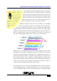
SmartBook for Renesas R8C/Tiny Microcontrollers 1.4 R8C/Tiny Architecture: As you already know, R8C/Tiny CPU is compatible with other M16C devices to maintain code compatibility. The architecture is derived using many registers. Basically these devices are meant for single chip operations because bus expansion facilities are not available with the controller. The program memory space is made available within the device. The internal bus width is 8 bits.
SmartBook for Renesas R8C/Tiny Microcontrollers registers, A0 and A1 for manipulating address generation. These R0-R3, address regis- registers are meant for different kinds of addressing. They ters, A0 and A1 and can also be used for data transfers and arithmetic/logic 4 D esi gn Data D a ta frame base register, FB form a bank of operations. Then there are 16-bit Base Registers, Frame Base Register (FB) and Static Base Register (SB) used registers.
SmartBook for Renesas R8C/Tiny Microcontrollers Carry (C) Flag: This flag retains a carry, borrow or shift out bit that has occurred in the arithmetic/logic operations. Debug (D) Flag: This D flag is used extensively for debugging purpose. During normal use, it must be set with 0. Zero (Z) Flag: This flag is set to 1 when an arithmetic operation resulted in 0.Otherwise, it is 0. Sign (S) Flag: This flag is set to 1 when an arithmetic operation resulting in a negative value. Otherwise, it is 0.
SmartBook for Renesas R8C/Tiny Microcontrollers Renesas Interrupt Table Register (INTB): This 20-bit register devices come with contains the address of an interrupt vector table. The more table may contain up to 63 interrupt vectors of 4 bytes 4 D esi gn Normally D a ta RAM area than other similar controllers. Because the large size, you can maintain of each. Using this INTB, this total interrupt space of 256 bytes (64x4) can be defined in any place in the memory space.
SmartBook for Renesas R8C/Tiny Microcontrollers Following is the address scheme for the memory organization. As you can see, the RAM area is made available at the lower end. Initial memory space, up to 02FFH is allotted for the Special Function Registers (SFR). SFR maintains all the peripheral functions’ control registers and other registers meant for flash programming and system management. Then the RAM area starts at 0400H and expands upwards.
4 Desig n SmartBook for Renesas R8C/Tiny Microcontrollers D a ta In the second mode first mode (E/W=0) is selected, the built in programming (E/W=1), you need kernel is transferred to the RAM area and then the not program control is shifted to this kernel. Without stopping transfer the programming kernel to the RAM. Keeping the programming the CPU, any portion of the flash memory can be reprogrammed. For this mode, the RAM area should be large enough to keep the programming kernel.
SmartBook for Renesas R8C/Tiny Microcontrollers Chapter 2. Clock Generating Mechanism 2.1 Introduction: R8C/Tiny microcontrollers sport a versatile clock generating mechanism to protect the controller’s operations against going awry on the account of system clock becoming faulty at any time.
4 Desig n SmartBook for Renesas R8C/Tiny Microcontrollers The micon contains clock to the high speed main clock source. This versatile low clock generating circuit is managed using a set of speed Ring Oscillator of about 125KHz and the D a ta high speed Ring registers. The clock generator also contains a set of dividers to generate many clock derivatives to suit different operating conditions. oscillator capable of generating the nominal clock signal of 8MHz 2.
SmartBook for Renesas R8C/Tiny Microcontrollers During stop mode, all clocks including the main clock are turned off. 2.3 On Chip Oscillator Clocks. The micons contain an on-chip oscillating circuitry that generates two clock sources: High speed on chip oscillator and Low speed on chip oscillator. These oscillators are selected by the bit, HR01 of HR0 register. After reset, the 2.
4 Desig n SmartBook for Renesas R8C/Tiny Microcontrollers D a ta The Micons deliver If the main clock stops oscillating when the OCD1 to OCD0 more bits in the OCD register are set to “11” (Oscillation Stop processing power with high speed s o u r c e s . When the operating speed is re- automatically starts operating, supplying the necessary clock to the microcomputer.
SmartBook for Renesas R8C/Tiny Microcontrollers These different operating modes are From the reset managed by proper initialization in few condition, Control Register 0), CM1 (System Clock Control Register 1), HR0 (High Speed On-chip Oscillator Control Register 0), OCD (Oscillation n 4 Desig selected registers: CM0 (System Clock the micon gets into high D a ta speed mode when the main clock is selected as the Stop Detection Register).
SmartBook for Renesas R8C/Tiny Microcontrollers 2.7 Wait Mode: Getting into the wait 4 Desig n mode is as easy as Getting into the wait mode is as easy as executing e x e c u t i n g t h e WA I T instruction D a ta point at of switched off and subsequently the CPU and the watchdog timer are turned off to conserve the power.
Like wait mode, to exit from this stop These devices also mode, a hardware reset or a peripheral contain a power on function interrupt is required. Only the reset function without before entering into stop mode can be any external device to used to bring the micon from the stop mode.
SmartBook for Renesas R8C/Tiny Microcontrollers the The R8C/Tiny controllers sport a versatile reset registers become zero facility to keep the controller working in the stable and the PC gets the reset conditions in spite of variations in the operating 4 Desig n After reset, v e c t o r. D a ta all Also all the ports are initialized for the inputs.
SmartBook for Renesas R8C/Tiny Microcontrollers internal reset condition is exited and the program is executed beginning with the address indicated by the reset vector FFFCH. The following figure indicates the reset sequence: Proper operating conditions are to be initialized to get this hardware reset ready. Voltage Detection Interrupt Register, D4INT, should be properly initialized for this purpose.
4 Desig n SmartBook for Renesas R8C/Tiny Microcontrollers D a ta VC13 bit indicates Like the Hardware Reset 2, the internal counter counts the status of supply low speed on chip oscillator upto 32 when the supply voltage at Vcc crosses Vdet and subsequently releases the internal reset. pin. It becomes zero The reset conditions of CPU, pins, registers are same as when that of Hardware Reset 1.
SmartBook for Renesas R8C/Tiny Microcontrollers Apart from VC27 of Voltage Detection Register 2, following bits play important role when using this voltage detection circuit. VC13: Voltage monitor flag of the register, Voltage Detection Register VCR1. This bit indicates the status of supply voltage at Vcc pin. It becomes zero when the supply voltage is less than Vdet and gets one level when the voltage rises to Vdet or more. This bit becomes valid only when VC27 is already set with the level 1.
SmartBook for Renesas R8C/Tiny Microcontrollers Voltage Detection Circuit should be enabled (set VC27 of VCR2 to 1) Voltage Detection Interrupt is enabled (set D40 of D4INT to 1) Voltage Detection Interrupt is selected (set D46 bit of D4INT is set to 0) Enable Voltage Detection Digital Filter (D41 bit of D4INT register) 0: Enable Digital Filter. 1: Disable Digital Filter.
SmartBook for Renesas R8C/Tiny Microcontrollers Chapter 3. Instruction Set 3.1 Introduction: In this chapter, we are going to discuss about the processing power of the R8C/Tiny microcontrollers. The processing power of the device is influenced by the respective instruction set and it plays a vital role in the application development process. A versatile and flexible instruction set can help the designers finish their application in less time using minimum code space.
SmartBook for Renesas R8C/Tiny Microcontrollers 4 D esi gn The instruction set D a ta of the R8C/Tiny contains 89 discreet instruc- tions. Of these, 20 instruc- tions require only one clock cycle for the execution. 75% of the instructions require 3.3 Instruction Set: less than five cycles for the execution. The instruction set of the R8C/Tiny contains 89 discreet instructions. Of these, 20 instructions require only one clock cycle for the execution.
SmartBook for Renesas R8C/Tiny Microcontrollers Decimal add with carry (DADC) Unsigned multiply (MULU) Decimal add without carry (DADD) Two’s complement (NEG) Decrement (DEC) Calculate sum of products (RMPA) Signed divide (DIV) Subtract with borrow (SBB) Unsigned divide (DIVU) Subtract without borrow (SUB) Signed divide extension (DIVX) 3.
SmartBook for Renesas R8C/Tiny Microcontrollers 3.8 Bit Manipulation (14): Logically AND bits (BAND) Exclusive OR inverted bits (BNXOR) Clear bits (BCLR) Logically OR bits (BOR) Conditional bit transfer (BMCnd) Set bit (BSET) Logically AND inverted bits (BNAND) Test bit (BTST) Logically OR inverted bits (BNOR) Test bit and clear (BTSTC) Invert bit (BNOT) Test bit and set (BTSTS) Test inverted bit (BNTST) Exclusive OR bits (BXOR) Transfer string backwards (SMOVB) Store string (SSTR) 3.
SmartBook for Renesas R8C/Tiny Microcontrollers Interrupt on overflow (INTO) Save context (STCTX) Transfer to control register (LDC) Interrupt for undefined instruction (UND) Restore context (LDCTX) Wait (WAIT) Transfer to INTB register (LDINTB) Now, we proceed further into a detailed discussion to get the complete picture on the processing power of the R8C/Tiny devices. The device handles the multiplying operations at a faster rate thanks to the builtin hardware 16 X 16 multiplier.
4 D esi gn SmartBook for Renesas R8C/Tiny Microcontrollers D a ta DADD instructions do DADD instructions do an arithmetic addition on BCD an arithmetic addition coded data and keeps the results in the destination. on BCD coded data and DADC instructions do the similar operation on the two keeps the results in the destination. Sum of Product (RMPA) operation gives the micon the MAC power that is available only in the regular and high priced DSP devices.
SmartBook for Renesas R8C/Tiny Microcontrollers 3.12 String Move Forward (SMOVF): This instruction transfer a data string from a 20 bit source address to a 16 bit destination address by successively incrementing the address. The transfer continues till the count in R3 comes down to zero. A single move operation consumes five clock cycles. SMOVF instruction transfer a data string from 3.
SmartBook for Renesas R8C/Tiny Microcontrollers 4 D esi gn The controllers sport a D a ta controllers sport a special instruction to save many special instruction, registers using a single instruction. The instruction does PUSHM to save many the data transfer to and from the stack area in less time registers using a single instruction. STCTX instruction takes with minimum program code. care of managing context details of about 256 tasks without much inputs from the designers.
SmartBook for Renesas R8C/Tiny Microcontrollers There is a complementary instruction, Load Context, LDCTX, also available to complete the picture. An example using STCTX and LDCTX instructions. 3.15 String Store (SSTR): This instruction stores the contents of R0 in block of memory area addressed by A1. The block length is defined by R3. This instruction takes 2 bytes of program code. 3.16 Extend Sign (EXTS): This extends the sign of the data in 16 or 32 bits using two to four bytes of code.
SmartBook for Renesas R8C/Tiny Microcontrollers 4 D esi gn The generic for- D a ta mat takes more code space, the other hand, the zero format requires least amount of code, may be a single byte to define the instruction. varying from two to eight bytes. The zero format requires least amount of code, may 3.17.1 Generic Format: This generic format can be used to define almost all the instructions of the micon. It takes two to eight bytes of code space.
SmartBook for Renesas R8C/Tiny Microcontrollers The facility to define the required instructions in different formats seems like a surprise to many designers. Many designers may also take the whole thing as a kind of waste of the device resources. But, R8C/Tiny designers have done lots of home work to create a way enabling the designers to finish their applications in their target memory size with the required speed and performance.
SmartBook for Renesas R8C/Tiny Microcontrollers www.MightyMicons.
SmartBook for Renesas R8C/Tiny Microcontrollers Chapter 4. Addressing Modes 4.1 Introduction: The facility to define the data that should be operated on and the target memory location plays an important role in the instruction set of the microcontrollers. With more options, the instruction set becomes very friendly to the system designers. The instruction set of the R8C/Tiny micons sports versatile and flexible addressing modes to empower the designers take control on the program flow without much efforts.
SmartBook for Renesas R8C/Tiny Microcontrollers These registers can be used individually or can be combined to form bigger size of data. The absolute mode gives direct address in the range 00000H to 0FFFFH using 16 bits. When using address register indirect, the contents of the address registers, A0 and A1 can be treated as the effective address required for the operations. In other relative modes, a displacement data plays a role in calculating the effective address of the memory location.
SmartBook for Renesas R8C/Tiny Microcontrollers to generate the effective address. In other two relative addressing modes, the displacement is added with Frame base register or the Stack pointer along with the sign bit to generate the effective address. If the result of this addition exceeds the range 00000H to 0FFFFH, all the bits above 16 are ignored and the address returns to either 00000H or 0FFFFH. This displacement is mentioned using a byte. 4.
4 D esi gn SmartBook for Renesas R8C/Tiny Microcontrollers D a ta The control regis- The address registers A0 and A1 are joined together to ter direct mode generate a 32 bit address when using 32 bit address register uses the regis- I N T B H , ISP, SP, SB, FB and FLG as the object of the pro- indirect mode. However, off these 32 bits, only lower 20 bits ters, INTBL, are considered to access the required memory location for the subsequent processing.
SmartBook for Renesas R8C/Tiny Microcontrollers Following are the options available to When using register access different bit positions: direct the 4 D esi gn mode, specified bit of the 1. Register direct. registers A0, A1, R0- 2. Absolute addressing. R3 becomes object 3. Address register indirect. 4. Address register relative. of D a ta the the processing. In the mode, absolute addressing the target bit is specified 5. SB relative. with reference to the bit zero 6. FB relative.
SmartBook for Renesas R8C/Tiny Microcontrollers the target bit in the device memory. Bits at the address range 00000H to 01FFFH can be specified for the boolean operations. When using address register relative mode, the contents of registers A0 and A1 is used to indicate the target bit from the bit zero position of the memory location indicated by the base register.
SmartBook for Renesas R8C/Tiny Microcontrollers bit can be located either above or below the address indicated by FB. When using FLG direct mode, different bits of the flag register can be accessed for the boolean operations. With this, we complete our discussion on the instruction set of the R8C/Tiny microcontrollers. Your attention is drawn towards the versatile and flexible instruction set of this micon, because this instruction set can be equated to the vocabulary of the language.
SmartBook for Renesas R8C/Tiny Microcontrollers Ne e Us 4 ws With the help of the rich vocabulary, any one can easily create a classical work without much strain. This applies well with the instruction set also!!. www.MightyMicons.
SmartBook for Renesas R8C/Tiny Microcontrollers Chapter 5. Interrupt Mechanism 5.1 Introduction: Interrupt facilities of the target microcontrollers plays a vital role in the system design. Professional designers may give a serious thought on these interrupt features to find out the suitability of the controller to use in a range of complicated applications. Lack of required interrupt power may even stall the project in the mid way.
4 D esi gn SmartBook for Renesas R8C/Tiny Microcontrollers D a ta Each of these interrupts is initiated. These interrupts also belong to the associated with a four byte hardware group. A few of the controller’s long Interrupt Vector. This instructions like Undefined Instruction (UND), vector contains starting Overflow (INTO), BRK and INT generate non- address of the service maskable interrupts. routine meant for that particular interrupt.
SmartBook for Renesas R8C/Tiny Microcontrollers 5.2.1 Undefined Instruction Interrupt. The micon generates an interrupt when executing the UND, undefined instruction, with the opcode of FFH, along the program flow. As you know, the un-programmed memory space of the R8C/Tiny controllers contains only FFH. Therefore, using this interrupt, a software protecting mechanism can be embedded into the applications to sense the unwanted control flow and subsequently do the needful correcting actions. 5.2.
SmartBook for Renesas R8C/Tiny Microcontrollers When any of these software interrupts in the range 0- 4 D esi gn The micon generates D a ta an interrupt 31 is executed, the U flag is saved in the stack and when executing the UND, then is cleared to make ISP active before starting the undefined instruction, interrupt service routine. This U flag is restored from the with the opcode of FFH. stack when returning from the service routine.
the bits AIER0 or AIER1 of the When the main clock is register, AIER. When this bit is set found not operating, this in- to one, the corresponding address terrupt is activated for fur- match register comes into picture. As ther processing.
SmartBook for Renesas R8C/Tiny Microcontrollers 4 D esi gn The maskable interrupts can D a ta be enabled or disabled using I flag of the FLG register. Each In general, you need to study the operations of the micon’s interrupt mechanism with care when of these interrupts is associated with an Interrupt Control Register, which contains infor- mation on the priority level in 3 bits known as ILVL0 to ILVL2 and the interrupt active condition in the bit IR (Interrupt Request bit).
SmartBook for Renesas R8C/Tiny Microcontrollers Now, we need to go back to interrupt sequence to know more about the workings of the interrupt mechanism. When an interrupt happens during the execution of an instruction, the micon finalizes the priority of that interrupt and shifts the programming control to that interrupt’s service routine after finishing the current instruction.
SmartBook for Renesas R8C/Tiny Microcontrollers all the interrupts are engaged or not available for further use. The D flag is cleared to zero to indicate that the single step interrupt is disabled. The U flag initialization is depending upon the interrupt number. This flag becomes zero for the interrupts up to 31 and the flag does not change for the software interrupts between 32 and 63 generated by the INT instruction. 4.
SmartBook for Renesas R8C/Tiny Microcontrollers 5.5.1 Saving the Registers in the Interrupt When Sequence. more interrupts or The controller saves the contents of the FLG with the same and PC registers in the stack during interrupt priority level sequence phase. Totally, a space of 4 bytes is 4 D esi gn two D a ta occur at the required to keep this information in the stack.
SmartBook for Renesas R8C/Tiny Microcontrollers As you know well, the interrupts levels of the maskable interrupts meant for the device’s peripheral functions can be set to the desired level using ILVL2-ILVL0 bits. When two or more interrupts with the same priority level occur at the same time, the hardware circuit built in the micon resolves the interrupt priority level.
SmartBook for Renesas R8C/Tiny Microcontrollers Analog to Digital Converter. INT2. UART1 Transmission. UART0 Transmission. Key Input. Lowest Priority Level. 5.5.3 External Hardware Interrupts. R8C/Tiny controllers have many external hardware interrupts, which can sense uncertain events in the target applications. They are known as INT interrupts, from INT0 to INT3. Like other interrupts, each of these interrupt is supported with an interrupt control register along with few other support registers.
4 D esi gn SmartBook for Renesas R8C/Tiny Microcontrollers D a ta There is a single interrupts are controlled by the KEIN register, which keeps instruction avail- the details like interrupt enabling/disabling and the polarity able (PUSHM type. and POPM), to push and pop important registers in a single shot with minimum code. all Along with four port lines, a key matrix of 4 x 4 size can be easily realized using these key interrupts.
SmartBook for Renesas R8C/Tiny Microcontrollers Chapter 6. Ports, Data Converters and Communication Facilities 6.1 Introduction: As you already know, Renesas microcontrollers are very popular for the rich set of peripheral functions. R8C/Tiny controllers sport plenty of I/O lines, range of 8/ 16 bit timer/counters, flexible communicating options like serial ports, IIC, SPI compatible ports, CAN and LIN facilities apart from multi channel 10 bit Analog to Digital converters.
4 D esi gn SmartBook for Renesas R8C/Tiny Microcontrollers D a ta Pull up control reg- Port data registers are the intermediate stage between the isters manage the CPU and the port lines managing the external events. connection of built- These registers come with input buffers and output latches in pull up resistors for all the available port lines. When the port lines are with the corresponding lines.
SmartBook for Renesas R8C/Tiny Microcontrollers Analog Input range : 0V to Vref. Operating modes : One shot and Repeat modes. Sample and Hold circuits : Available. Conversion time : Minimum 2.8µSec at 10MHz. Input channels : Depends on the device. Varying from 4 to 20. The A/D circuit has the software control to disconnect the Vref voltage from the converter circuit to reduce the power consumption. Also there is a facility to control A/D conversion rate by selecting different operating clocks.
SmartBook for Renesas R8C/Tiny Microcontrollers 4 D esi gn Each D a ta of independent of other each. generate the required clocks. The operation of the A/D converter is managed by three A/D They sport baud rate generators to transfer register. serial ports acts exclusive data The result of A/D conversion is available in the 16 bit AD these control registers. The A/D conversion is started or stopped by setting the bit ADST of A/D control register 0.
SmartBook for Renesas R8C/Tiny Microcontrollers 6.32 Clock Asynchronous Serial Mode. • Data Length: 7 or 8 or 9 bits with one or two stop bits. • Also parity bit can be defined from these options: Odd, Even or none. • Flexible clock options: f2SIO, f8SIO and f32SIO or external clock. • Interrupt request can be generated for transmit buffer empty condition, transmit end and reception end conditions. • Error indicating flags are available: overrun, framing, parity and error sum conditions. 6.
SmartBook for Renesas R8C/Tiny Microcontrollers Under this mode, each receiving processor is addressed by an ID. A serial communication cycle consists of an ID sending cycle that identifies the receiving processor and then a data sending cycle. The multiprocessor bit distinguishes ID cycles from the data cycles. The master processor starts by sending the ID of the receiving processor with which it wants to communicate with multiprocessor bit set to 1.
SmartBook for Renesas R8C/Tiny Microcontrollers 6.4.1 IIC Bus Interface. • Selectable master or slave modes. • Continuous transmit or receive operation. • Start and stop bits are automatically generated when defined as master. • Bit synchronization/wait function. • N-channel open drain output for direct drive of SCL and SDA pins. • Overrun error detection. • Up to 6 sources of interrupt requests: Slave – Address – Match, transmit-end, receive data full, arbitration lost, etc… 6.4.2 SSU Bus interface.
SmartBook for Renesas R8C/Tiny Microcontrollers www.MightyMicons.
SmartBook for Renesas R8C/Tiny Microcontrollers Chapter 7. Timer/Counter Functions 7.1 Introduction: The Timer and Counter functions of any microcontroller play an active role in system design. These facilities enable the designers manage many difficult tasks with ease and confidence. This part of the series gives a complete picture on the R8C/Tiny Microcontroller’s timing features.
SmartBook for Renesas R8C/Tiny Microcontrollers Programmable one shot generation mode: This mode generates a one shot pulse under the control of either software or the hardware trigger. Programmable wait one shot generation mode: A mono shot pulse is generated with a definable delay after getting the trigger command. Input capture mode: In this mode, counting of the timer is captured with reference to the presence of the active input pulse signals at the timer input pins.
SmartBook for Renesas R8C/Tiny Microcontrollers 7.2 Timer Mode: Most of the timers of the R8C/Tiny have this mode. This helps the designers generate different time delays or generate the interrupts at the regular intervals. The 8-bit timers are formed using an 8 bit timing mechanism along with an 8 bit prescalar. These timers have an 8 bit prescalar cascaded with the timing register. Every underflow of this prescalar decrements a count in the 8 bit timing register.
4 D esi gn SmartBook for Renesas R8C/Tiny Microcontrollers D a ta When configured prescalar down. When the prescalar underflows, the count for value of the timer register decrements by one and at the same the event counter mode, the timers start counting the external signals connected time the prescalar is set automatically by the contents of the reload register and the counting operation keeps going. When the timing register underflows, an interrupt is generated.
The event counter mode is available in In pulse width measure- Timer X and Timer RA. The external sig- ment mode, either high nal is applied to INT1/CNTR0 pin of the level or the low level of Timer X and INT1/TRAIO pin of the Timer the input signal can be RA. When the timing register underflows, measured using the an interrupt also can be generated for further processing.
SmartBook for Renesas R8C/Tiny Microcontrollers 4 D esi gn With the pulse period mea- D a ta surement mode , the timer counts down all the input signals between either two rising or falling edges. When the timers are configured for the pulse output mode , the underflow of the timing register changes the output level at the specified pins 7.5 Pulse Period Measurement Mode: This mode of operation is similar to the pulse width measuring mode with a difference.
tion, the initial state of the output pin, In waveform generating CNTR0, can be defined to meet the re- mode, the duty cycle of quirements. the square waveform can be varied. The The other timer with this facility, Timer RA, has two output pins: TRAIO and comple- timing register gets alternate ment output of TRAIO. 4 D esi gn SmartBook for Renesas R8C/Tiny Microcontrollers D a ta reload values from both TYPR and TYSC registers. Because of this facility, 7.
4 D esi gn SmartBook for Renesas R8C/Tiny Microcontrollers D a ta Programmable one ters. Because of this facility, square waveform with differ- shot generation mode ent primary and secondary width can be generated. Hence, generates one shot you get a variable duty cycle. pulse of either high or low level at the output pin. This pulse is activated by The output level during the primary and secondary width can be defined for all these timers.
SmartBook for Renesas R8C/Tiny Microcontrollers For the hardware trigger signal, the polarity can also be selected either as rising or falling edge. Timer ignores any other trigger signals till it finishes the counting down operation. 7.9 Programmable Wait One Shot Generation Mode: This is similar to other one shot mode with a difference. In this mode, a delay can be introduced before generating the target one shot pulse after the active trigger signal.
SmartBook for Renesas R8C/Tiny Microcontrollers Under this mode, the 16 bit timer is initialized to operate in free running counter with the selected internal clock. Input signal is applied at the pin, INT3/TCIN of the controller. Polarity of the input signal that should capture the free running counter also to be defined. After the start command, the timer starts counting upwards from zero.
Now, we discuss the operation of this timer For every match with using Timer C as reference. the compare register, timer As you know well, Timer C is based on 16 output pin changes its level and bit counter running from zero with the selected at the same time input clock signal.
4 D esi gn SmartBook for Renesas R8C/Tiny Microcontrollers D a ta The RD timer has two channels 7.12 PWM Mode of Timer RD: of 16 bit timers, which always When the timers of R8C/Tiny micon are config- count upwards. Each of these channels can control up to 4 output lines and generates PWM waveforms in three of these port lines.
SmartBook for Renesas R8C/Tiny Microcontrollers match functions of the RD timer. Each of the compare registers has its own port lines which changes the state when the contents of that particular register matches with the timer’s counting register, TRDi. Normally, compare match values meant for the active level of the PWM signals are loaded into these registers. TRDGRA1 determines the period of the PWM waveform in general. Then the timer counter TRDi is kept initialized to zero.
SmartBook for Renesas R8C/Tiny Microcontrollers The status of all these compare match operations are indicated by the corresponding flag bits in the Timer Status Register. These flags are set to one level when the match is established during the counting operation. Similarly, these compare match conditions can also be used to generate the interrupts. 7.13 PWM3 Mode of Timer RD: PWM3 mode of almost similar to PWM mode of the timer with few differences.
SmartBook for Renesas R8C/Tiny Microcontrollers Initially, both the PWM output pins are in the inactive levels. First, both TRDGRB1 and TRDGRA1 registers are compared with the contents of timer counter, TRD0. For the compare match with the register, TRDGRB1, the output pin, TRDIOB0 is set to its active level and the counting continues upwards. At the same time, when a match condition happens for the register, TRDGRA1, the output pin TRDIOA0 is set to its defined active level.
4 D esi gn SmartBook for Renesas R8C/Tiny Microcontrollers D a ta The RD timer, when config- To get the required PWM signals properly, the fol- ured in the Reset Synchro- lowing conditions are to be met in the program: nous mode generates three (TRDGRB1 ) < ( TRDGRB0 ) < ( TRDGRA0 ) and ( sets of PWM waveforms TRDGRA1 ) < ( TRDGRA0). along with the pulse signal indicating fre- 7.14 Reset Synchronous PWM Mode: quency of the PWM signal.
SmartBook for Renesas R8C/Tiny Microcontrollers The period of the PWM signal is 1/fk * ( m+1) where m is the count value kept in the TRDGRA0 register and fk is the selected frequency for the counting operation. For the counter phase wave, the active level is 1/fk * ( n+1). For this discussion, low level is taken as the active level. But, for the signal generation, either low or high level can be defined as the active level.
4 D esi gn SmartBook for Renesas R8C/Tiny Microcontrollers D a ta The complementary Whenever the contents of the timer register, TRD0, PWM mode intro- matches with the contents of the predefined compare reg- duces a dead time isters, the corresponding output pins change the state to in the counter phase signals. pulse width.
SmartBook for Renesas R8C/Tiny Microcontrollers pare match register, TRDGRA0 and then get decremented for the next PWM period as indicated in the following figure. Because of this kind of arrangement, these PWM waveforms contain center aligned active output levels. Like other types of PWM modes, three compare registers; TRDGRB0, TRDGRA1 and TRDGRB1 contain the data relevant to the three sets of complementary PWM waveforms. Following indicates the period calculation for these PWM signals.
SmartBook for Renesas R8C/Tiny Microcontrollers When the contents of registers, TRD0 and TRDGRA0 matches, the timer registers start counting downwards. During this downward counting, all the outputs get inactive levels for all the match conditions. The PWM period signal gets toggled whenever the timer register, TRD0 matches with the value of TRDGRA0.
SmartBook for Renesas R8C/Tiny Microcontrollers 7.16 Real Time Clock: Real time clock function is available with the timer RE and it generates one second signals. When the timer RE is configured for this mode, timer gets the required clock signal from the externally connected crystal of 32.768 KHz. The required one second signal is generated through a set of dividing registers and is fed to next level of registers to track other timing parameters like minutes, hours and week.
SmartBook for Renesas R8C/Tiny Microcontrollers www.MightyMicons.
SmartBook for Renesas R8C/Tiny Microcontrollers Chapter 8. R8C/Tiny Micon Information 8.1 R8C/Tiny Micon Roadmap: www.MightyMicons.
SmartBook for Renesas R8C/Tiny Microcontrollers 8.2 R8C/18-1B Group Features: 8.3 R8C/20-23 Group Features: www.MightyMicons.
SmartBook for Renesas R8C/Tiny Microcontrollers 8.4 R8C/24-25 Group Features: 8.5 R8C/26-29 Group Features: www.MightyMicons.
SmartBook for Renesas R8C/Tiny Microcontrollers 8.6 R8C/2A-2D Group Features: www.MightyMicons.
SmartBook for Renesas R8C/Tiny Microcontrollers Supplementary Information for the SmartBook. Kindly Keep visiting the following support page for this SmartBook to get more useful information on the R8C/Tiny tools and documents developed by us. www.MightyMicons.com/html/R8CTinyResources.htm www.MightyMicons.
SmartBook for Renesas R8C/Tiny Microcontrollers www.MightyMicons.com www.MightyMicons.