
Datasheet


R07DS0161EJ0500 Rev.5.00 Page 1 of 9
Apr 19, 2012
Preliminary Datasheet
RJH60D3DPE
600V - 17A - IGBT
Application: Inverter
Features
Short circuit withstand time (5 s typ.)
Low collector to emitter saturation voltage
V
CE(sat)
= 1.6 V typ. (at I
C
= 17 A, V
GE
= 15 V, Ta = 25°C)
Built in fast recovery diode (100 ns typ.) in one package
Trench gate and thin wafer technology
High speed switching
t
f
= 70 ns typ. (at V
CC
= 300 V, V
GE
= 15 V, I
C
= 17 A, Rg = 5 , Ta = 25°C, inductive load)
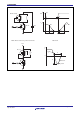
Outline
1. Gate
2. Collecto
r
3. Emitter
4. Collecto
r
RENESAS Package code:
PRSS0004AE-B
(Package name:
LDPAK (S)-(1) )
1
2
3
4
C
G
E
Absolute Maximum Ratings
(Ta = 25°C)
Item Symbol Ratings Unit
Collector to emitter voltage / diode reverse voltage V
CES
/ V
R
600 V
Gate to emitter voltage V
GES
±30 V
Tc = 25°C I
C
35 A Collector peak current
Tc = 100°C I
C
17 A
Collector peak current ic(peak)
Note1
70 A
Collector to emitter diode forward current i
DF
17 A
Collector to emitter diode forward peak current i
DF
(peak)
Note1
70 A
Collector dissipation P
C
Note2
113 W
Junction to case thermal resistance (IGBT) j-c
Note2
1.11 °C/ W
Junction to case thermal resistance (Diode j-cd
Note2
2.8 °C/ W
Junction temperature Tj 150 °C
Storage temperature Tstg –55 to +150 °C
Notes: 1. PW 10 s, duty cycle 1%
2. Value at Tc = 25C
R07DS0161EJ0500
Rev.5.00
Apr 19, 2012