User’s Manual SuperH™ Family E10A-USB Emulator User’s Manual (HS0005KCU01H, HS0005KCU02H) SuperH™ Family E10A-USB HS0005KCU01HE All information contained in these materials, including products and product specifications, represents information on the product at the time of publication and is subject to change by Renesas Electronics Corporation without notice.
Notice 1. Descriptions of circuits, software and other related information in this document are provided only to illustrate the operation of semiconductor products and application examples. You are fully responsible for the incorporation of these circuits, software, and information in the design of your equipment. Renesas Electronics assumes no responsibility for any losses incurred by you or third parties arising from the use of these circuits, software, or information. 2.
Regulatory Compliance Notices z European Union regulatory notices This product complies with the following EU Directives. (These directives are only valid in the European Union.) CE Certifications: • Electromagnetic Compatibility (EMC) Directive 2004/108/EC EN 55022 Class A WARNING: This is a Class A product. In a domestic environment this product may cause radio interference in which case the user may be required to take adequate measures.
z United States Regulatory notices This product complies with the following EMC regulation. (This is only valid in the United States.) FCC Certifications: This equipment has been tested and found to comply with the limits for a Class A digital device, pursuant to Part 15 of the FCC Rules. These limits are designed to provide reasonable protection against harmful interference when the equipment is operated in a commercial environment.
IMPORTANT INFORMATION READ FIRST • READ this user's manual before using this emulator product. • KEEP the user's manual handy for future reference. Do not attempt to use the emulator product until you fully understand its mechanism. Emulator Product: Throughout this document, the term "emulator product" shall be defined as the following products produced only by Renesas Electronics Corp. excluding all subsidiary products.
LIMITED WARRANTY Renesas warrants its emulator products to be manufactured in accordance with published specifications and free from defects in material and/or workmanship. Renesas, at its option, will replace any emulator products returned intact to the factory, transportation charges prepaid, which Renesas, upon inspection, shall determine to be defective in material and/or workmanship. The foregoing shall constitute the sole remedy for any breach of Renesas’ warranty.
State Law: Some states do not allow the exclusion or limitation of implied warranties or liability for incidental or consequential damages, so the above limitation or exclusion may not apply to you. This warranty gives you specific legal rights, and you may have other rights which may vary from state to state.
SAFETY PAGE READ FIRST • READ this user's manual before using this emulator product. • KEEP the user's manual handy for future reference. Do not attempt to use the emulator product until you fully understand its mechanism. DEFINITION OF SIGNAL WORDS This is the safety alert symbol. It is used to alert you to potential personal injury hazards. Obey all safety messages that follow this symbol to avoid possible injury or death.
WARNING Observe the precautions listed below. Failure to do so will result in a FIRE HAZARD and will damage the user system and the emulator product or will result in PERSONAL INJURY. The USER PROGRAM will be LOST. 1. Do not repair or remodel the emulator product by yourself for electric shock prevention and quality assurance. 2. Always switch OFF the host computer and user system before connecting or disconnecting any CABLES or PARTS. 3.
Warnings on Emulator Usage Be sure to read and understand the warnings below before using this emulator. Note that these are the main warnings, not the complete list. WARNING Always switch OFF the host computer and user system before connecting or disconnecting any CABLES or PARTS. Failure to do so will result in a FIRE HAZARD and will damage the user system and the emulator product or will result in PERSONAL INJURY. The USER PROGRAM will be LOST.
Introduction The High-performance Embedded Workshop is a powerful development environment for embedded applications targeted at Renesas microcontrollers. The main features are: • A configurable build engine that allows you to set-up compiler, assembler and linker options via an easy to use interface. • An integrated text editor with user customizable syntax coloring to improve code readability. • A configurable environment to run your own tools.
About This Manual This manual describes preparation before using the emulator, emulator functions, debugging functions specific to the emulator, tutorial, and emulator's hardware and software specifications. Refer to the High-performance Embedded Workshop User's Manual for details on the information on the basic usage of the High-performance Embedded Workshop, customization of the environment, build functions, and debugging functions common to each High-performance Embedded Workshop product.
User Registration When you install debugger software, a text file for user registration is created on your PC. Fill it in and email it to your local distributor. If you have replaced an emulator main unit or emulation probe, rewrite an emulator name and serial number in the text file you filled in earlier to register your new hardware products. Your registered information is used for only after-sale services, and not for any other purposes.
Table of Contents Section 1 Overview................................................................................................................................ 1 1.1 1.2 1.3 Warnings ................................................................................................................................................................... 3 Environmental Conditions ....................................................................................................................................
5.1 Setting the Environment for Emulation ................................................................................................................ 105 5.1.1 Opening the [Configuration] Dialog Box................................................................................................... 105 5.1.2 [General] Page............................................................................................................................................ 106 5.1.3 Downloading to the Flash Memory..
5.6.10 Extracting Records from the Acquired Information ................................................................................... 153 5.6.11 Analyzing Statistical Information............................................................................................................... 160 5.6.12 Extracting Function Calls from the Acquired Trace Information............................................................... 162 5.7 Analyzing Performance...................................................
6.20 Stack Trace Function ............................................................................................................................................ 243 6.21 Performance Measurement Function .................................................................................................................... 245 6.21.1 Performance Measurement Function.......................................................................................................... 245 6.21.2 Profiling Function ......
SuperH™ Family E10A-USB Emulator Section 1 Overview Section 1 Overview The E10A-USB emulator (hereafter referred to as the emulator) is a support tool for developing application systems to run on Renesas original microcomputers. The main unit of the emulator is connected, through the dedicated debugging interface, to the user system. The user system can be debugged under the conditions similar to the actual application conditions. The emulator enables debugging anywhere indoors or out.
SuperH™ Family E10A-USB Emulator Section 1 Overview The emulator provides the following features: • Excellent cost-performance emulator Compactness and connection to the USB are implemented. • Realtime emulation Realtime emulation of the user system is enabled at the maximum operating frequency of the CPU. • Excellent operability Using the High-performance Embedded Workshop enables user program debugging using a pointing device such as a mouse.
SuperH™ Family E10A-USB Emulator 1.1 Section 1 Overview Warnings CAUTION READ the following warnings before using the emulator product. Incorrect operation will damage the user system and the emulator product. The USER PROGRAM will be LOST. 1. Check all components against the component list after unpacking the emulator. 2. Never place heavy objects on the casing. 3. Protect the emulator from excessive impacts and stresses. For details, refer to section 1.2, Environmental Conditions. 4.
SuperH™ Family E10A-USB Emulator 1.2 Section 1 Overview Environmental Conditions CAUTION Observe the conditions listed in tables 1.1 and 1.2 when using the emulator. Failure to do so will cause illegal operation in the user system, the emulator product, and the user program. Table 1.
SuperH™ Family E10A-USB Emulator Section 1 Overview Table 1.2 lists the acceptable operating environments. Table 1.2 Operating Environments ® Item 32-Bit Editions of Windows XP 32-Bit Editions of Windows ® Vista or 32-Bit or 64-Bit ® Editions of Windows 7 Host computer Built-in Pentium III or higher-performance CPU (1 GHz or higher recommended); IBM PC or compatible machine with USB 1.1/2.0 (FullSpeed).
SuperH™ Family E10A-USB Emulator R20UT0870EJ1000 Rev. 10.
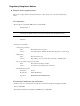
SuperH™ Family E10A-USB Emulator Section 2 Emulator Functions Section 2 Emulator Functions This section describes the emulator functions. They differ according to the device supported by the emulator. For the usage of each function, refer to section 6, Tutorial. 2.1 Overview Table 2.1 gives a functional overview of the emulator. For details on the functions of each product, refer to the online help. Table 2.1 Emulator Functions No.
SuperH™ Family E10A-USB Emulator Section 2 Emulator Functions Table 2.1 Emulator Functions (cont) No. Item Function 5 Performance measurement function • Uses a counter in the device to measure the number of cycles that passes during point-to-point execution. • Measures the number of cycles that pass in executing individual functions and lists them at the end of execution from a ‘Go’ command.
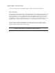
SuperH™ Family E10A-USB Emulator Section 2 Emulator Functions The specific functions of the emulator are described in the next section. 2.2 Trace Functions The emulator has two trace functions. 2.2.1 Internal Trace Function The branch source and branch destination addresses, mnemonics, operands, and source lines are displayed. This function uses the trace buffer built into the device. Notes: 1. The number of branch instructions that can be acquired by a trace differs according to the product.
SuperH™ Family E10A-USB Emulator 2.2.2 Section 2 Emulator Functions AUD Trace Function This is the large-capacity trace function that is enabled when the AUD pins are connected to the emulator. When an event that starts trace acquisition occurs, the trace information is output in realtime from the AUD pins. This function is only available on the E10A-USB emulator with model name HS0005KCU02H.
SuperH™ Family E10A-USB Emulator Section 2 Emulator Functions (2) Trace acquisition mode The AUD trace function has the following modes to acquire a trace. Table 2.2 shows the AUD trace acquisition mode that can be set in each trace function. Table 2.
SuperH™ Family E10A-USB Emulator Section 2 Emulator Functions (3) Trace display contents When the program breaks, the following trace results are displayed in the [Trace] window. • PTR: The trace-buffer pointer (+0 from the last instruction to have been executed) • IP: Indicates the number of cycles that have elapsed since the latest trace information was gathered. For branch instructions, the branch source and destination are counted together as one.
SuperH™ Family E10A-USB Emulator Section 2 Emulator Functions The following items will be displayed, according to the device to be debugged. For specifications of the individual products, refer to the additional document, Supplementary Information on Using the SHxxxx, or the online help. • PTR: The trace-buffer pointer (+0 from the last instruction to have been executed) • IP: Indicates the number of cycles that have elapsed since the latest trace information was gathered.
SuperH™ Family E10A-USB Emulator Section 2 Emulator Functions Table 2.
SuperH™ Family E10A-USB Emulator 2.2.4 Section 2 Emulator Functions Useful Functions of the [Trace] Window The trace window provides the following useful functions. (1) Searches for the specified data. (2) Extracts the specified data. (3) Filters and displays again the specified data. (4) Supplements the information from the branch destination address to the next branch source address. For the usage of those functions, refer to section 5.6, Viewing the Trace Information.
SuperH™ Family E10A-USB Emulator Section 2 Emulator Functions (3) Forced break function Forcibly breaks the user program. 2.4 Performance Measurement Function The emulator has two types of performance measurement functions. 2.4.1 Function for Measuring the Number of Cycles from Point to Point This function applies a counter in the device to measure the number of cycles from one specified condition being satisfied until a next specified condition is satisfied.
SuperH™ Family E10A-USB Emulator 2.5 Section 2 Emulator Functions Memory Access Functions The emulator has the following memory access functions. (1) Memory read/write function [Memory] window: The memory contents are displayed in the window. Only the amount specified when the [Memory] window is opened can be read. Since there is no cache in the emulator, read cycles are always generated.
SuperH™ Family E10A-USB Emulator Section 2 Emulator Functions (6) Monitoring function In some devices to be debugged, memory contents can be monitored during user program execution. For details on the specifications of each product, refer to the online help.
SuperH™ Family E10A-USB Emulator 2.6 Section 2 Emulator Functions Stack Trace Function The emulator uses the information on the stack to display the names of functions in the sequence of calls that led to the function to which the program counter is currently pointing. This function can be used only when the load module that has the Dwarf2-type debugging information is loaded. For the usage of this function, refer to section 6.20, Stack Trace Function. 2.
SuperH™ Family E10A-USB Emulator R20UT0870EJ1000 Rev. 10.
SuperH™ Family E10A-USB Emulator Section 3 Preparation before Use Section 3 Preparation before Use 3.1 Emulator Preparation Unpack the emulator and prepare it for use as follows: WARNING READ the reference sections shaded in figure 3.1 before using the emulator product. Incorrect operation will damage the user system and the emulator product. The USER PROGRAM will be LOST. Reference Unpack the emulator Component list Check the components against the component list When the emulator is used first.
SuperH™ Family E10A-USB Emulator 3.2 Section 3 Preparation before Use Emulator Hardware Configuration As shown in figure 3.2, the emulator consists of an emulator, a USB cable, and a user system interface cable. The emulator is connected to the host computer via USB 1.1, and also to the USB port conforming to USB 2.0. Figure 3.2 Emulator Hardware Configuration (when the 36-pin Type Connector is Used) R20UT0870EJ1000 Rev. 10.
SuperH™ Family E10A-USB Emulator Section 3 Preparation before Use The names of each section of the emulator are explained next. Emulator Top View: Figure 3.3 Emulator Top View (a) E10A-USB logo plate: A yellow plate (for HS0005KCU01H) or a red plate (for HS0005KCU02H) dedicated for the emulator is provided to be easily distinguished from other E-series emulators. (b) Sliding switch cover: A cover to protect switches for setting the emulator, which is closed to prevent incorrect operation.
SuperH™ Family E10A-USB Emulator Section 3 Preparation before Use Emulator Host-side View: Figure 3.4 Emulator Host-side View (a) Host-side connector: R20UT0870EJ1000 Rev. 10.00 Aug 10, 2012 A USB connector for the host computer. Be sure to connect the provided USB cable.
SuperH™ Family E10A-USB Emulator Section 3 Preparation before Use Emulator User-side View: Figure 3.5 Emulator User-side View (a) User-side connector: R20UT0870EJ1000 Rev. 10.00 Aug 10, 2012 A user system interface cable is connected.
SuperH™ Family E10A-USB Emulator Section 3 Preparation before Use Emulator Bottom View: (a) MODEL : HS0005KCU02H (HS0005KCU02H) SERIAL No. : 00001A This device complies with Part 15 of the FCC Rules. Operation is subject to the follow ing two conditions: (1) This device may not cause harmful interference, and (2) This device must accept any interference received, including interference that may cause undesired operation.
SuperH™ Family E10A-USB Emulator 3.3 Section 3 Preparation before Use CD-R The root directory of the CD-R contains a setup program for installing the emulator’s software. The folders contain the files and programs listed below. Table 3.1 Contents of the CD-R Directories Directory Name Contents ® Description Dlls Microsoft runtime library A runtime library for the High-performance Embedded Workshop.
SuperH™ Family E10A-USB Emulator 3.5 Section 3 Preparation before Use Connecting the Emulator to the Host Computer This section describes how to connect the emulator to the host computer. For the position of each connector of the emulator, refer to section 3.2, Emulator Hardware Configuration. Note: Be sure to install the software for the emulator before putting the emulator in place.
SuperH™ Family E10A-USB Emulator Section 3 Preparation before Use The emulator is connected to the host computer via the USB 1.1, and also to the USB port conforming to USB 2.0. Figure 3.7 shows the system configuration. Figure 3.7 System Configuration when Connecting the Emulator to the Host Computer R20UT0870EJ1000 Rev. 10.
SuperH™ Family E10A-USB Emulator 3.6 Section 3 Preparation before Use Connecting the Emulator to the User System Use the procedure below to connect the emulator to the user system with the user system interface cable, or to disconnect them when moving the emulator or the user system. 1. Check that the host computer is turned off or the emulator is not connected to the host computer with the USB cable. 2. Connect the user system interface cable to the user-side connector of the emulator. 3.
SuperH™ Family E10A-USB Emulator Section 3 Preparation before Use (1) The connector must be installed to the user system. Table 3.2 shows the recommended connector for the emulator. Table 3.2 Recommended H-UDI Port Connector Connector Type Number Manufacturer Specifications 14-pin connector 2514-6002 Minnesota Mining & Manufacturing Ltd. 14-pin straight type 36-pin connector DX10M-36S Hirose Electric Co., Ltd. Screw type DX10M-36SE, DX10GM-36SE Lock-pin type Notes: 1.
SuperH™ Family E10A-USB Emulator Section 3 Preparation before Use H-UDI port connector Pin 1 User system User system interface cable Figure 3.9 Connecting the User System Interface Cable to the User System when the 36-pin Type Connector is Used User system interface cable Tab GND line H-UDI port connector Pin 8 User system GND connection Pin 1 User system Figure 3.10 Connecting the User System Interface Cable to the User System when the 14-pin Type Connector is Used R20UT0870EJ1000 Rev. 10.
SuperH™ Family E10A-USB Emulator Section 3 Preparation before Use CAUTION Note that the pin number assignments of the connector differ from those of the connector manufacturer. Notes: 1. Connection of the signals differs depending on the package. For details, refer to the device’s pin assignments. 2. To remove the 14-pin type user system interface cable from the user system, pull the tab on the connector upward. 3.
SuperH™ Family E10A-USB Emulator H-UDI port Section 3 Preparation before Use SHxxxx TDI TDO JTAG port H-UDI IC TDI IC TDO TDI TAP IC TDI TDO TAP TDO TAP Boundary scan loop User system TDI: Test data input TDO: Test data output TAP: Test access port Figure 3.11 User System Example R20UT0870EJ1000 Rev. 10.
SuperH™ Family E10A-USB Emulator 3.7 Section 3 Preparation before Use Connecting System Ground WARNING Separate the frame ground from the signal ground at the user system. Failure to do so will result in a FIRE HAZARD and will damage the user system and the emulator product or will result in PERSONAL INJURY. The emulator's signal ground is connected to the user system's signal ground. In the emulator, the signal ground and frame ground are connected.
SuperH™ Family E10A-USB Emulator 3.8 Section 3 Preparation before Use Setting the DIP Switches WARNING Do not change switches (SW2 and SW3) while the emulator and the user sytem are turned on. The changing of switches (SW2 and SW3) will result in a FIRE HAZARD and will damage the user system and the emulator product. The USER PROGRAM will be LOST.
SuperH™ Family E10A-USB Emulator Section 3 Preparation before Use USER I/F RENESAS B US 0A E1 1 0 ACT 1 0 1 1 2 2 3 3 ON OFF Figure 3.13 DIP Switches Notes: 1. When the VCC pin (I/O power supply) on the user system is connected to the UVCC pin, the emulator is able to operate at the same voltage level of the user interface as VCC. 2. The /CA pin is only supported by the SH-Mobile microcomputers. 3.
SuperH™ Family E10A-USB Emulator Section 3 Preparation before Use • Settings for use of the 36-pin interface cable Description: When the VCC (I/O power supply related to the H-UDI) of the user system is connected to the UVCC pin of the H-UDI port connector, set the UVCC with the power supplied. Here, the I/O voltage of the user interface applies to the ranges between 1.8 V to 5.0 V. If the VCC is not connected, set the UVCC as disconnected. Table 3.
SuperH™ Family E10A-USB Emulator Section 3 Preparation before Use Table 3.5 Switch Settings of the E10A-USB (Using SH-3/SH-4 Series 36-pin Interface) Switch Settings State of the E10A-USB SW1 SW2 SW3 Userinterface I/O Voltage Signal to be Connected to Pin 15 Signal to be Connected to Pin 29 0 (off) - - - - - The emulator is only set up 1 (on) 0 (off) 1 (on) 3.3 V fixed N.C. N.C. UVCC is disconnected 1 (on) 1 (on) 1.8 V to 5.0 V N.C.
SuperH™ Family E10A-USB Emulator Section 3 Preparation before Use • Settings for use of the 14-pin interface cable Description: When the VCC (I/O power supply related to the H-UDI) of the user system is connected to the UVCC pin of the H-UDI port connector, set the UVCC with the power supplied. Here, the I/O voltage of the user interface applies to the ranges between 1.8 V to 5.0 V. If the VCC is not connected, set the UVCC as disconnected. Table 3.
SuperH™ Family E10A-USB Emulator Section 3 Preparation before Use Table 3.10 Switch Settings of the E10A-USB (Using SH-3/SH-4 Series 14-pin Interface) Switch Settings State of the E10A-USB SW1 SW2 SW3 Userinterface I/O Voltage Signal to be Connected to Pin 8 Signal to be Connected to Pin 11 0 (off) - - - - - The emulator is only set up 1 (on) 0 (off) 1 (on) 3.3 V fixed N.C. N.C. UVCC is disconnected 1 (on) 1 (on) 1.8 V to 5.0 V N.C.
SuperH™ Family E10A-USB Emulator 3.9 Section 3 Preparation before Use Interface Circuits in the Emulator Figures 3.14 through 3.17 show interface circuits in the emulator. Use them as a reference to determine the value of the pull-up resistance. Note: The 74LVC2G125 operates at 3.3 V or VCC (1.8 to 5.0 V) from the H-UDI port connector (changed by the switch). R20UT0870EJ1000 Rev. 10.
SuperH™ Family E10A-USB Emulator Section 3 Preparation before Use Emulator control circuit 3.3 V SW2, SW3 H-UDI port connector UVCC 74LVC2G125 10 kΩ Vcc A Y 22 Ω TCK 74LVC2G125 10 kΩ Vcc A Y 74AVC16245 74LVC2G125 Vcc 22 Ω TRST 1.8 V 10 kΩ 22 Ω B A 74AVC16245 B A TDO Y A 74LVC2G125 1.8 V Vcc 22 Ω Y A 10 kΩ ASEBRK/BRKACK 74LVC2G125 Vcc A Y 74LVC2G125 10 kΩ Vcc A Y 22 Ω TMS 74LVC2G125 10 kΩ Vcc A Y 74AVC16245 B A 74LVC2G125 Vcc Y A 22 Ω TDI 1.8 V 10 kΩ 22 Ω RESET Figure 3.
SuperH™ Family E10A-USB Emulator Section 3 Preparation before Use 3.3 V SW2, SW3 Emulator control circuit H-UDI port connector UVCC 74LVC2G125 74AVC16245 B A 74AVC16245 B A 74AVC16245 B A 74AVC16245 B A 1.8 V 10 kΩ Vcc Y A 22 Ω AUDCK 74LVC2G125 1.8 V Vcc 22 Ω Y A 10 kΩ 74LVC2G125 1.8 V Vcc 22 Ω Y A 10 kΩ 74LVC2G125 1.8 V Vcc 22 Ω Y A 10 kΩ AUDATA[3:0] AUDSYNC AUDATA[7:4] Figure 3.
SuperH™ Family E10A-USB Emulator Section 3 Preparation before Use Emulator control circuit 3.3 V H-UDI port connector SW2 UVCC 74LVC2G125 10 kΩ Vcc A Y 22 Ω TCK 74LVC2G125 10 kΩ Vcc A Y 74AVC16245 74LVC2G125 Vcc 22 Ω TRST 1.8 V 10 kΩ 22 Ω B A 74AVC16245 B A TDO Y A 74LVC2G125 1.8 V Vcc 22 Ω Y A 10 kΩ ASEBRKAK 74LVC2G125 Vcc A Y 74LVC2G125 10 kΩ Vcc A Y 22 Ω TMS 74LVC2G125 10 kΩ Vcc A Y 74LVC2G125 74AVC16245 B A 74AVC16245 B A 22 Ω 1.
SuperH™ Family E10A-USB Emulator Section 3 Preparation before Use 3.3 V H-UDI port connector Emulator control circuit SW2 UVCC 74LVC2G125 74AVC16245 B A 1.8 V 10 kΩ Vcc Y A 22 Ω AUDCK 74LVC2G125 Vcc A Y 74AVC16245 B A 74LVC2G125 1.8 V Vcc 22 Ω Y A 10 kΩ AUDATA[3:0] 74LVC2G125 Vcc A Y 74AVC16245 B A 74LVC2G125 1.8 V Vcc 22 Ω Y A 10 kΩ AUDSYNC 74LVC2G125 Vcc A Y 74AVC16245 B A 74LVC2G125 1.8 V Vcc 22 Ω Y A 10 kΩ AUDMD 74LVC2G125 Vcc A Y 74LVC2G125 74AVC16245 B A 1.
SuperH™ Family E10A-USB Emulator 3.10 Section 3 Preparation before Use Setting up the Emulator Set up the emulator’s firmware using the following procedures. Note: Only one device group can be set up using the setup tool when the emulator is purchased. Be sure to check the device group you have selected on the label for product management attached to the back of the emulator box. To use the emulator for another device group after set up, purchase the license tool to add a device group.
SuperH™ Family E10A-USB Emulator 3.10.1 Section 3 Preparation before Use Setting up at Purchasing the Emulator or Updating the Version of Software Note: If you are using the HS0005KCU01H (serial No.: 03311C or later) or HS0005KCU02H (serial No.: 04146E or later) emulator hardware, the below procedure may not be required; follow the procedure only when the dialog box shown in figure 3.18 or 3.19 is displayed by using the procedure described in section 3.11, System Check. Figure 3.
SuperH™ Family E10A-USB Emulator Section 3 Preparation before Use Figure 3.20 [Start] Menu Figure 3.21 Setup Tool for Emulator (a) Device group of the emulator firmware: Name of the device group currently set. (b) Version number of the emulator firmware: The version number of software for controlling the SHxxxx group in the emulator. This item is displayed only when the SHxxxx group is available. (c) Version number of the setup program: The version number of the setup program. R20UT0870EJ1000 Rev.
SuperH™ Family E10A-USB Emulator Section 3 Preparation before Use Notes: 1. If the version numbers shown in (b) and (c) are the same, setup of the emulator is not required. Setup the emulator only when “-.-.--.---“ is shown in (b) or the version number of (b) is older than that of (c). 2. If an emulator other than the SHxxxx E10A-USB is connected, the following error message will be displayed to exit the setup tool. Figure 3.22 Error Message 3.
SuperH™ Family E10A-USB Emulator Section 3 Preparation before Use 4. Turn the setup switch (SW1) to ‘0’, connect the USB cable again, and click the [OK] button. Setting up the emulator’s firmware is started. Notes: 1. If the following dialog message is displayed, insert the USB cable again. Figure 3.25 [Setup tool for SHxxxx E10A-USB Emulator] Dialog Box 2. When [Add New Hardware Wizard] is displayed, select [Install the software automatically]. 3.
SuperH™ Family E10A-USB Emulator Section 3 Preparation before Use 5. When the following dialog box is displayed, setting up the emulator is completed. Figure 3.27 Message for Completion of Setting up the Emulator 6. When setting up the emulator has been completed, the following message will be displayed. Turn the setup switch (SW1) to ‘1’, connect the USB cable again, and click the [OK] button. Figure 3.28 [Setup Tool for SHxxxx E10A-USB Emulator] Dialog Box Notes: 1.
SuperH™ Family E10A-USB Emulator 3.10.2 Section 3 Preparation before Use Setting up the Emulator by Using the License Tool to Add a Device Group In the license tool, the emulator for the current product group can be used for debugging another product group (device group such as SHxxxx Device Group, H8S Device Group, or H8SX Device Group that is supported by the emulator).
SuperH™ Family E10A-USB Emulator Section 3 Preparation before Use (2) Setting up the emulator 1. Open the sliding switch cover and check that the switch (SW1) for setting the emulator is turned to ‘1’. 2. Select [Renesas] -> [License tool for E10A-USB] -> [H8S Device Group] from [Programs] in the [Start] menu. This starts up the license tool to add a device group to the emulator. Figure 3.29 [Start] Menu Figure 3.
SuperH™ Family E10A-USB Emulator Section 3 Preparation before Use Notes: 1. If the version numbers shown in (b) and (c) are the same, setup of the emulator is not required. Set up the emulator only when “-.-.--.---“ is shown in (b) or the version number of (b) is older than that of (c). 2. If the following error message is displayed, the host computer is not connected to the emulator or the setup switch (SW1) is turned to ‘0’. Figure 3.
SuperH™ Family E10A-USB Emulator Section 3 Preparation before Use Notes: 1. If the following dialog message is displayed, insert the USB cable again. Figure 3.33 [License tool for H8S E10A-USB Emulator] Dialog Box 2. When [Add New Hardware Wizard] is displayed, select [Install the software automatically]. 3. Although a dialog box will be displayed to indicate disconnection of the USB, this is not a problem.
SuperH™ Family E10A-USB Emulator Section 3 Preparation before Use 5. When the following dialog box is displayed, setting up the emulator is completed. Figure 3.35 Message for Completion of Setting up the Emulator 6. When setting up the emulator has been completed and the following message is displayed, turn the setup switch (SW1) to ‘1’, connect the USB cable again, and click the [OK] button. Figure 3.36 [License tool for H8S E10A-USB Emulator] Dialog Box Notes: 1.
SuperH™ Family E10A-USB Emulator 3.11 Section 3 Preparation before Use System Check When the software is executed, use the procedure below to check that the emulator is connected correctly. Here, use the workspace for a tutorial provided on the product. Refer to section 4, Preparations for Debugging, for the other activating method to create a new project or use an existing workspace. 1. Connect the emulator to the host computer. 2.
SuperH™ Family E10A-USB Emulator Section 3 Preparation before Use 5. The [Welcome!] dialog box is displayed. Figure 3.38 [Welcome!] Dialog Box [Create a new project workspace] radio button: Creates a new workspace. [Open a recent project workspace] radio button: Uses an existing workspace and displays the history of the opened workspace. [Browse to another project workspace] radio button: Uses an existing workspace; this radio button is used when the history of the opened workspace does not remain.
SuperH™ Family E10A-USB Emulator Section 3 Preparation before Use After the directory has been specified, select the following file and click the [Open] button. Figure 3.39 [Open Workspace] Dialog Box 6. The [CPU Select] dialog box is displayed. Figure 3.40 [CPU Select] Dialog Box The [CPU Select] dialog box has the following options. • [Search the best JTAG clock] check box Search the JTAG clock values and start up with the highest available value as the initial value.
SuperH™ Family E10A-USB Emulator Section 3 Preparation before Use 7. The [Select Emulator mode] dialog box is displayed depending on the MCU/MPU used. Figure 3.41 [Select Emulator mode] Dialog Box Select the MCU/MPU name in use from the [Device] drop-down list box. The following items are selectable in the [Mode] group box. ⎯ E10A-USB Emulator The E10A-USB emulator for the specified MCU/MPU is activated. Debugging the program is enabled.
SuperH™ Family E10A-USB Emulator Section 3 Preparation before Use 8. The [Connecting] dialog box is displayed and the emulator connection is started. Figure 3.42 [Connecting] Dialog Box 9. The dialog box shown in figure 3.43 is displayed if no product groups have been installed in the emulator at the time of purchase or if the SHxxxx license has been installed in the emulator but the emulator firmware has been set up for a different device group. The dialog box shown in figure 3.
SuperH™ Family E10A-USB Emulator Section 3 Preparation before Use Figure 3.44 Dialog Box to Confirm Updating of the SHxxxx Emulator Firmware CAUTION The USB cable must not be disconnected until writing is complete. Early disconnection may damage the emulator. Note: The above dialog boxes are only displayed if you are using the HS0005KCU01H (serial No.: 03311C or later) or HS0005KCU02H (serial No.: 04146E or later) emulator hardware. In this case, follow the procedure described in section 3.10.
SuperH™ Family E10A-USB Emulator Section 3 Preparation before Use 13. If no reset signal is detected, the following dialog box is displayed. Figure 3.46 [Can not find /RESET signal] Dialog Box When the [Ignore] button is clicked, the emulator issues a reset in the CPU for initiation. However, this method is unavailable for some products. For details, refer to section 2.2, Specific Functions for the Emulator when Using the SHxxxx, in the additional document, Supplementary Information on Using the SHxxxx.
SuperH™ Family E10A-USB Emulator Section 3 Preparation before Use 15. After the following dialog box is displayed, input the ID code as a security code for the flash memory. However, H’FFFFFFFF is disabled as the ID code. Input this ID code when [E10A-USB Emulator] is selected and the [New ID code] check box is unselected on activating the emulator. If the ID code is not matched or the [New ID code] check box is selected, the flash memory contents are erased. Figure 3.48 [ID Code] Dialog Box 16.
SuperH™ Family E10A-USB Emulator Section 3 Preparation before Use Notes: 1. If the emulator is not initiated, the following dialog boxes shown in figures 3.50 through 3.56 will be displayed. (a) If the following dialog box is displayed and the method 11 above is unavailable, the power of the user system may not be input or the RESET signal may not be input to the device. Check the input circuits for the power of the user system and the reset pin. Figure 3.
SuperH™ Family E10A-USB Emulator Section 3 Preparation before Use (c) If the following dialog box is displayed, the emulator’s firmware may not be set up correctly. Set up the firmware of the device group that is used for the setup tool or license tool. Figure 3.52 [The product currently connected] Dialog Box (d) If the following dialog box is displayed, the version of the firmware in the emulator may be old. Set up the firmware by using the setup tool. Figure 3.
SuperH™ Family E10A-USB Emulator Section 3 Preparation before Use (e) If the following dialog box is displayed, the device may not correctly operate. Check if there are reasons for illegal device operation. Figure 3.54 [COMMUNICATION TIMEOUT ERROR] Dialog Box Figure 3.55 [INVALID ASERAM FIRMWARE!] Dialog Box Figure 3.56 [Error JTAG boot] Dialog Box R20UT0870EJ1000 Rev. 10.
SuperH™ Family E10A-USB Emulator Section 3 Preparation before Use (f) The following dialog box is displayed when the flash memory cannot be erased. Change the MCU since the flash memory has been reprogrammed more times than the limitation. Figure 3.57 [Flash memory erase error!] Dialog Box Note: If a mode is illegally set, the error message shown in figure 3.57 will be displayed. (g) The following dialog box is displayed when the flash memory cannot be reprogrammed.
SuperH™ Family E10A-USB Emulator Section 3 Preparation before Use (h) The following dialog box is displayed when an incorrect ID code has been input. For security, the flash memory is completely erased. Figure 3.59 [ID code error!] Dialog Box (i) The following dialog box is displayed when the MCU cannot communicate with the emulator. The MCU may not operate correctly; check the MCU settings. Figure 3.60 [Boot Failed!] Dialog Box R20UT0870EJ1000 Rev. 10.
SuperH™ Family E10A-USB Emulator Section 3 Preparation before Use 2. If an incorrect driver has been selected, the following dialog box will appear. Figure 3.61 [Unable to restore the previous driver settings] Dialog Box 3. If the emulator is not activated due to other reasons, a message box corresponding to the status is displayed. Use the message as a reference to check the wiring on the board. R20UT0870EJ1000 Rev. 10.
SuperH™ Family E10A-USB Emulator R20UT0870EJ1000 Rev. 10.
SuperH™ Family E10A-USB Emulator Section 4 Preparations for Debugging Section 4 Preparations for Debugging 4.1 Method for Activating High-performance Embedded Workshop To activate the High-performance Embedded Workshop, follow the procedure listed below. 1. Connect the emulator to the host computer and the user system, then turn on the user system. 2. Select [High-performance Embedded Workshop] from [Renesas] -> [High-performance Embedded Workshop] of [Programs] in the [Start] menu. 3.
SuperH™ Family E10A-USB Emulator Section 4 Preparations for Debugging In this section, we describe the following three ways to start up the High-performance Embedded Workshop: • [Create a new project workspace] - a toolchain is not in use • [Create a new project workspace] - a toolchain is in use • [Browse to another project workspace] The operation of [Open a recent project workspace] radio button is same as the operation without specifying the workspace file when [Browse to another project workspa
SuperH™ Family E10A-USB Emulator Section 4 Preparations for Debugging 2. The Project Generator is started. In this section, we omit description of the settings for the toolchain. If you have not purchased the toolchain, the following dialog box is displayed. Figure 4.3 [New Project Workspace] Dialog Box [Workspace Name] edit box: Enter the new workspace name. Here, for example, enter ‘test’. [Project Name] edit box: Enter the project name.
SuperH™ Family E10A-USB Emulator Section 4 Preparations for Debugging 3. Make the required setting for the toolchain. When the setting has been completed, the following dialog box is displayed. Figure 4.4 [Setting the Target System for Debugging] Dialog Box Check the target emulator and click the [Next] button. For details on the items that can be selected in this dialog box, refer to the file titled “MPUs and MCUs Supported by the E10A-USB Emulator” (esupportdevice.
SuperH™ Family E10A-USB Emulator Section 4 Preparations for Debugging 4. Set the configuration file name. The configuration file saves the state of High-performance Embedded Workshop except for the emulator. Figure 4.5 [Setting the Debugger Options] Dialog Box This is the end of the emulator setting. Click the [Finish] button to exit the Project Generator. The High-performance Embedded Workshop is activated.
SuperH™ Family E10A-USB Emulator 4.1.2 Section 4 Preparations for Debugging Creating the New Workspace (Toolchain Used) 1. In the [Welcome!] dialog box that is displayed when the High-performance Embedded Workshop is activated, select [Create a new project workspace] radio button and click the [OK] button. Figure 4.6 [Welcome!] Dialog Box R20UT0870EJ1000 Rev. 10.
SuperH™ Family E10A-USB Emulator Section 4 Preparations for Debugging 2. The Project Generator is started. If you have purchased the toolchain, the following dialog box is displayed. Figure 4.7 [New Project Workspace] Dialog Box [Workspace Name] edit box: Enter the new workspace name. Here, for example, enter ‘test’. [Project Name] edit box: Enter the project name. When the project name is the same as the workspace name, it needs not be entered.
SuperH™ Family E10A-USB Emulator Section 4 Preparations for Debugging 3. Make the required setting for the toolchain. When the setting has been completed, the following dialog box is displayed. Figure 4.8 [New Project –7/9– Setting the Target System for Debugging] Dialog Box Check the target emulator and click the [Next] button. For details on the items that can be selected in this dialog box, refer to the file titled “MPUs and MCUs Supported by the E10A-USB Emulator” (esupportdevice.
SuperH™ Family E10A-USB Emulator Section 4 Preparations for Debugging 4. Set the configuration file name. The configuration file saves the state of High-performance Embedded Workshop except for the emulator. Figure 4.9 [New Project –8/9– Setting the Debugger Options] Dialog Box This is the end of the emulator setting. Exit the Project Generator according to the instructions on the screen. The High-performance Embedded Workshop is activated. 5.
SuperH™ Family E10A-USB Emulator Section 4 Preparations for Debugging (a) Connecting the emulator after the setting at emulator activation Select [Debug settings] from the [Debug] menu to open the [Debug Settings] dialog box. It is possible to register the download module or the command chain that is automatically executed at activation. For details on the [Debug Settings] dialog box, refer to section 4.3, Setting at Emulator Activation.
SuperH™ Family E10A-USB Emulator 4.1.3 Section 4 Preparations for Debugging Selecting an Existing Workspace 1. In the [Welcome!] dialog box that is displayed when the High-performance Embedded Workshop is activated, select [Browse to another project workspace] radio button and click the [OK] button. Figure 4.11 [Welcome!] Dialog Box 2. The [Open Workspace] dialog box is displayed. Select a directory in which you have created a workspace. After that, select the workspace file (.
SuperH™ Family E10A-USB Emulator Section 4 Preparations for Debugging Figure 4.12 [Open Workspace] Dialog Box 3. This activates the High-performance Embedded Workshop and recovers the state of the selected workspace at the time it was saved. When the saved state information of the selected workspace includes connection to the emulator, the emulator will automatically be connected. To connect the emulator when the saved state information does not include connection to the emulator, refer to section 4.
SuperH™ Family E10A-USB Emulator 4.2 Setting at Emulator Activation 4.2.1 Setting at Emulator Activation Section 4 Preparations for Debugging When the emulator is activated, the command chain can be automatically executed. It is also possible to register multiple load modules to be downloaded. The registered load modules are displayed on the workspace window. 1. Select [Debug settings] from the [Debug] menu to open the [Debug Settings] dialog box. Figure 4.
SuperH™ Family E10A-USB Emulator Section 4 Preparations for Debugging 4. Click the [Options] tab. Figure 4.14 [Debug Settings] Dialog Box ([Options] Page) The command chain that is automatically executed at the specified timing is registered.
SuperH™ Family E10A-USB Emulator 4.2.2 Section 4 Preparations for Debugging Downloading a Program A download module is added under [Download modules] in the [Workspace] window. Open the load module of [Download modules] in the [Workspace] window by clicking the righthand mouse button and select [Download module] to start downloading the module. Figure 4.15 Download Menu of the [Workspace] Window ([Projects]) Notes: 1.
SuperH™ Family E10A-USB Emulator 4.2.3 Section 4 Preparations for Debugging Setting the Writing Flash Memory Mode The following describes the procedures when the emulator is used as a tool for programming of the internal ROM. The load module to be downloaded to the new workspace is registered and programmed. Note: 1. When the [Writing Flash memory] mode is selected, command chains registered on the [Options] page of the [Debug Settings] dialog box must be removed.
SuperH™ Family E10A-USB Emulator Section 4 Preparations for Debugging Figure 4.16 [New Project Workspace] Dialog Box R20UT0870EJ1000 Rev. 10.
SuperH™ Family E10A-USB Emulator Section 4 Preparations for Debugging (b) Select the target MCU and click the [Next] button. Figure 4.17 [New Project –7/9– Setting the Target System for Debugging] Dialog Box R20UT0870EJ1000 Rev. 10.
SuperH™ Family E10A-USB Emulator Section 4 Preparations for Debugging (c) The [Select Emulator mode] dialog box is displayed. Figure 4.18 [Select Emulator mode] Dialog Box Select the [Writing Flash memory] mode. (d) Turn on the target board, input the reset signal from the user system, and press the [OK] button. Figure 4.19 Dialog Box of the RESET Signal Input Request Message R20UT0870EJ1000 Rev. 10.
SuperH™ Family E10A-USB Emulator Section 4 Preparations for Debugging (e) For the [Clock] dialog box, set the frequency of the crystal oscillator which has been connected to or the external clock which has been input to the target microcomputer (MCU). Figure 4.20 [Clock] Dialog Box (f) Select [Debug Setting] from the [Debug] menu. Figure 4.21 High-performance Embedded Workshop Window R20UT0870EJ1000 Rev. 10.
SuperH™ Family E10A-USB Emulator Section 4 Preparations for Debugging (g) Select the target MCU and then the download module with the [Add…] button. Figure 4.22 [Debug Setting] Dialog Box ([Target] Page) (h) The download file is displayed on [Project Files]. Figure 4.23 [Workspace] Window ([Project Files]) R20UT0870EJ1000 Rev. 10.
SuperH™ Family E10A-USB Emulator Section 4 Preparations for Debugging (i) Select and download the file with the right-hand mouse button. Figure 4.24 Download Menu of the [Workspace] Window ([Project Files]) (j) The dialog box for sum checking is displayed and programming is completed. Sum data is a value that data in the internal ROM area has been added by byte. If no user program exists, the value is calculated by H’FF. Figure 4.25 Message for Completion of Flash Memory Programming R20UT0870EJ1000 Rev.
SuperH™ Family E10A-USB Emulator Section 4 Preparations for Debugging (k) When the following dialog box is displayed, click on the [OK] button. The debugging platform is automatically disconnected. Figure 4.26 Message for Exiting Writing Flash Memory Mode and Automatic Disconnection R20UT0870EJ1000 Rev. 10.
SuperH™ Family E10A-USB Emulator 4.3 Section 4 Preparations for Debugging Debug Sessions The High-performance Embedded Workshop stores all of your builder options into a configuration. In a similar way, the High-performance Embedded Workshop stores your debugger options in a session. The debugging platforms, the programs to be downloaded, and each debugging platform’s options can be stored in a session. Sessions are not directly related to a configuration.
SuperH™ Family E10A-USB Emulator Section 4 Preparations for Debugging • From the dialog box 1. Select [Debug -> Debug Sessions…]. This will open the [Debug Sessions] dialog box (figure 4.28). Figure 4.28 [Debug Sessions] Dialog Box 2. Select the session you want to use from the [Current session] drop-down list. 3. Click the [OK] button to set the session. R20UT0870EJ1000 Rev. 10.
SuperH™ Family E10A-USB Emulator 4.3.2 Section 4 Preparations for Debugging Adding and Removing Sessions A new session can be added by copying settings from another session or removing a session. • To add a new empty session 1. Select [Debug -> Debug Sessions…] to display the [Debug Sessions] dialog box (figure 4.28). 2. Click the [Add…] button to display the [Add new session] dialog box (figure 4.29). 3. Check the [Add new session] radio button. 4. Enter a name for the session. 5.
SuperH™ Family E10A-USB Emulator Section 4 Preparations for Debugging • To import an existing session into a new session file 1. Select [Debug -> Debug Sessions…] to display the [Debug Sessions] dialog box (figure 4.28). 2. Click the [Add…] button to display the [Add new session] dialog box (figure 4.29). 3. Check the [Use an existing session file] radio button. 4. Enter a name for the session. 5.
SuperH™ Family E10A-USB Emulator Section 4 Preparations for Debugging • To view the session properties 1. Select [Debug -> Debug Sessions…] to display the [Debug Sessions] dialog box (figure 4.28). 2. Select the session you would like to view the properties for. 3. Click the [Properties] button to display the [Session Properties] dialog box (figure 4.30). Figure 4.30 [Session Properties] Dialog Box • To make a session read-only 1.
SuperH™ Family E10A-USB Emulator Section 4 Preparations for Debugging Figure 4.31 [Save Session] Dialog Box 4.3.3 Saving Session Information • To save a session Select [File -> Save Session]. R20UT0870EJ1000 Rev. 10.
SuperH™ Family E10A-USB Emulator 4.4 Section 4 Preparations for Debugging Connecting the Emulator Select either of the following two ways to connect the emulator: (a) Connecting the emulator after the setting at emulator activation Select [Debug settings] from the [Debug] menu to open the [Debug Settings] dialog box. It is possible to register the download module or the command chain that is automatically executed at activation. For details on the [Debug Settings] dialog box, refer to section 4.
SuperH™ Family E10A-USB Emulator 4.5 Section 4 Preparations for Debugging Reconnecting the Emulator When the emulator is disconnected, use the following way for reconnection: Select [Debug -> Connect] or click the [Connect] toolbar button ( ). The emulator is connected. Note: The emulator must be selected in the [Target] drop-down list box of the [Debug Settings] dialog box (see figure 4.
SuperH™ Family E10A-USB Emulator R20UT0870EJ1000 Rev. 10.
SuperH™ Family E10A-USB Emulator Section 5 Debugging Section 5 Debugging This section describes the debugging operations and their related windows and dialog boxes. 5.1 Setting the Environment for Emulation 5.1.1 Opening the [Configuration] Dialog Box Selecting [Setup -> Emulator -> System…] or clicking the [Emulator System] toolbar button ( opens the [Configuration] dialog box. R20UT0870EJ1000 Rev. 10.
SuperH™ Family E10A-USB Emulator 5.1.2 Section 5 Debugging [General] Page Sets the emulator operation conditions. Figure 5.1 [Configuration] Dialog Box ([General] Page) R20UT0870EJ1000 Rev. 10.
SuperH™ Family E10A-USB Emulator Section 5 Debugging Items that can be displayed in the sheet are listed below. [Mode] Displays the MCU/MPU name. [Emulation mode] Selects the emulation mode at user program execution. Select Normal to perform normal emulation. Select No break to disable PC breakpoint or break condition settings during emulation. [Step option] Sets the step interrupt option. Disable interrupts during single step execution: Disables interrupts* during step execution.
SuperH™ Family E10A-USB Emulator 5.1.3 Section 5 Debugging Downloading to the Flash Memory Sets the emulator operation conditions for downloading the external flash memory. This function is not available when the SH7047F, SH7144F, or SH7145F is in use. For details, refer to section 6.22, Downloading to the Flash Memory Area. Figure 5.2 [Configuration] Dialog Box ([Loading flash memory] Page) R20UT0870EJ1000 Rev. 10.
SuperH™ Family E10A-USB Emulator Section 5 Debugging Items that can be displayed in the sheet are listed below. [Loading flash memory] Sets Enable for flash memory downloading. At Enable, when the flash memory is downloaded on the High-performance Embedded Workshop, the write module is always called. Disable: Not download to the flash memory Enable: Download to the flash memory [Erasing flash memory] Sets Enable for erasing before the flash memory is programmed.
SuperH™ Family E10A-USB Emulator 5.2 Section 5 Debugging Downloading a Program This section describes how to download a program and view it as source code or assemblylanguage mnemonics. Note: After a break has been detected, the High-performance Embedded Workshop displays the location of the program counter (PC). In most cases, for example if an Elf/Dwarf2-based project is moved from its original path, the source file may not be automatically found.
SuperH™ Family E10A-USB Emulator 5.2.2 Section 5 Debugging Viewing the Source Code Select your source file and click the [Open] button to make the High-performance Embedded Workshop open the file in the integrated editor. It is also possible to display your source files by double-clicking on them in the [Workspace] window. Figure 5.3 [Source] Window R20UT0870EJ1000 Rev. 10.
SuperH™ Family E10A-USB Emulator Section 5 Debugging In this window, the following items are shown on the left as line information. The first column (Source address column): Address information The second column (Event column): Event information (event condition) The third column (S/W breakpoint column): PC, bookmark, and breakpoint information Source address column When a program is downloaded, an address for the current source file is displayed on the Source address column.
SuperH™ Family E10A-USB Emulator Section 5 Debugging S/W breakpoint column S/W breakpoint column displays the following items: : A bookmark is set. : A PC Break is set. : PC location To switch off a column in all source files 1. Click the right-hand mouse button on the [Source] window or select the [Edit] menu. 2. Click the [Define Column Format…] menu item. 3. The [Global Editor Column States] dialog box is displayed. 4. A check box indicates whether the column is enabled or not.
SuperH™ Family E10A-USB Emulator 5.2.3 Section 5 Debugging Viewing the Assembly-Language Code Click the [Disassembly] toolbar button at the top of the window when a source file is opened to show the assembly-language code that corresponds to the current source file. If you do not have a source file, but want to view code in the assembly-language level, either choose [View] -> [Disassembly…] or click the [Disassembly] toolbar button ( ).
SuperH™ Family E10A-USB Emulator 5.2.4 Section 5 Debugging Modifying the Assembly-Language Code You can modify the assembly-language code by double-clicking on the instruction that you want to change. The [Assembler] dialog box will be opened. Figure 5.7 [Assembler] Dialog Box The address, machine code, and disassembled instruction are displayed. Enter the new instruction or edit the current instruction in the [Mnemonic] field.
SuperH™ Family E10A-USB Emulator 5.2.5 Section 5 Debugging Viewing a Specific Address When you are viewing your program in the [Disassembly] window, you may want to look at another area of your program's code. Rather than scrolling through a lot of code in the program, you can go directly to a specific address. Double-click on the address in the [Disassembly] window or select [Set Address…] from the popup menu, and the dialog box shown in figure 5.8 is displayed. Figure 5.
SuperH™ Family E10A-USB Emulator 5.3 Section 5 Debugging Displaying Memory Contents in Realtime Use the [Monitor] window to monitor the memory contents during user program execution. Note: This function is not supported in some devices to be debugged. For details on the specifications of each product, refer to the online help. 5.3.1 Opening the [Monitor] Window To open the [Monitor] window, select [View -> CPU -> Monitor -> Monitor Setting...
SuperH™ Family E10A-USB Emulator Section 5 Debugging [Name]: Decides the name of the monitor window. [Options]: Sets monitor conditions. [Address]: Sets the start address for monitoring. [Size]: Sets the range for monitoring. [Access]: Sets the access size to be displayed in the monitor window. [Auto-Refresh at rate]: Sets the interval for acquisition by monitoring. [Reading the Initial Value]: Selects reading of the values in the monitored area when the monitor window is opened.
SuperH™ Family E10A-USB Emulator [History]: Section 5 Debugging Displays the previous settings. Note: Selection of the foreground or background color may not be available depending on the operating system in use. After setting, clicking the [OK] button displays the [Monitor] window. Figure 5.10 [Monitor] Window During user program execution, the display is updated according to the setting value of the autoupdate interval.
SuperH™ Family E10A-USB Emulator 5.3.3 Section 5 Debugging Temporarily Stopping Update of the Monitor During user program execution, the display of the [Monitor] window is automatically updated according to the auto-update interval. Select [Lock Refresh] from the popup menu of the [Monitor] window to stop the update of display. The characters in the address section are displayed in black, and the update of display is stopped. Selecting [Lock Refresh] again from the popup menu cancels the stopped state.
SuperH™ Family E10A-USB Emulator 5.3.6 Section 5 Debugging Hiding the [Monitor] Window When using the Monitor function to monitor the value of a variable from the [Watch] window, hide the [Monitor] window for the effective use of the screen. The current monitoring information is listed as the submenu when selecting [Display -> CPU -> Monitor]. The list consists of the [Monitor] window name and the address to start monitoring. When the left of the list is checked, the [Monitor] window is being displayed.
SuperH™ Family E10A-USB Emulator 5.3.7 Section 5 Debugging Managing the [Monitor] Window Selecting [Display -> CPU -> Monitor -> Windows Select…] displays the [Windows Select] dialog box. In this window, the current monitoring condition is checked and the new monitoring condition is added, edited, and deleted in succession. Selecting multiple monitoring conditions enables a temporary stop of update, hiding, and deletion. Figure 5.12 [Windows Select] Dialog Box R20UT0870EJ1000 Rev. 10.
SuperH™ Family E10A-USB Emulator 5.4 Section 5 Debugging Viewing the Current Status Choose [View -> CPU -> Status] or click the [View Status] toolbar button ( [Status] window and see the current status of the debugging platform. ) to open the Figure 5.13 [Status] Window The [Status] window has three sheets: • [Memory] sheet Contains information about the current memory status including the memory-mapping resources and the areas used by the currently loaded object file.
SuperH™ Family E10A-USB Emulator 5.5 Section 5 Debugging Using the Event Points The emulator has the event point function that performs breaking, tracing, and execution time measurement by specifying more complex conditions along with the PC breakpoints standard for the High-performance Embedded Workshop. 5.5.1 PC Breakpoints When the instruction of the specified address is fetched, the user program is stopped. Up to 255 points can be set. 5.5.
SuperH™ Family E10A-USB Emulator 5.5.3 Section 5 Debugging Opening the [Event] Window Select [View -> Code -> Eventpoints] or click the [Eventpoints] toolbar button ( [Event] window. ) to open the The [Event] window has the following two sheets: [Breakpoint] sheet: Displays the settings made for PC breakpoints. It is also possible to set, modify, and cancel PC breakpoints. [Event condition] sheet: Displays or sets the settings made for event condition channels. 5.5.
SuperH™ Family E10A-USB Emulator Section 5 Debugging This window displays and sets the breakpoints. Items that can be displayed in the sheet are listed below.
SuperH™ Family E10A-USB Emulator 5.5.8 Section 5 Debugging Disable Disables the selected breakpoint(s). When a breakpoint is disabled, the breakpoint will remain in the list; when specified conditions have been satisfied, a break will not occur. 5.5.9 Delete Removes the selected breakpoint. To retain the details of the breakpoint but not have it cause a break when its conditions are met, use the Disable option (see section 5.5.8, Disable). 5.5.10 Delete All Removes all breakpoints. 5.5.
SuperH™ Family E10A-USB Emulator 5.5.12 Section 5 Debugging [Breakpoint] Dialog Box Figure 5.15 [Breakpoint] Dialog Box This dialog box specifies break conditions. A breakpoint address to be set is specified in the [Value] edit box. The PC register can also be specified such as #PC. Up to 255 breakpoints can be specified. The contents to be set differ depending on the product. For details, refer to the on-line help for each product.
SuperH™ Family E10A-USB Emulator 5.5.13 Section 5 Debugging Setting Event Conditions On the [Event condition] sheet, the settings for event conditions are displayed, modified, and added. Figure 5.16 [Event] Window ([Event condition] Sheet) This window displays and sets the break condition. Since the number of channels for detecting conditions and the contents to be set differ depending on the product, refer to the on-line help for each product. Items that can be displayed in the sheet are listed below.
SuperH™ Family E10A-USB Emulator [Action] Section 5 Debugging Operation of the emulator when a break condition is satisfied. Break: Breaks program execution When a breakpoint is double-clicked in this window, the [Event condition] dialog box is opened and break conditions can be modified. For details on the [Event condition] dialog box, refer to the on-line help for each product. A popup menu containing the following options is available by right-clicking within the window. 5.5.14 Edit...
SuperH™ Family E10A-USB Emulator 5.5.19 Section 5 Debugging Go to Source Only enabled when one event channel is selected. Opens the [Source] window at address of event channel. If an address value has not been set to the event channel, this option cannot be used. 5.5.20 [Combination action(Sequential PtoP)] Sets a sequential condition of event channels or points where performance measurement or internal tracing starts and stops. 5.5.
SuperH™ Family E10A-USB Emulator 5.5.25 Section 5 Debugging Deleting Event Conditions Select an event condition and choose [Delete] from the popup menu to remove the selected event condition. To retain the event condition but not have it cause an event when its conditions are met, use the [Disable] option (see section 5.5.24, Disabling Event Conditions). 5.5.26 Deleting All Event Conditions Choose [Delete All] from the popup menu to remove all event conditions. 5.5.
SuperH™ Family E10A-USB Emulator 5.6 Section 5 Debugging Viewing the Trace Information For the description on the trace function, refer to section 2.2, Trace Functions. 5.6.1 Opening the [Trace] Window To open the [Trace] window, choose [View -> Code -> Trace] or click the [Trace] toolbar button ( ). 5.6.2 Acquiring Trace Information When the emulator does not set the acquisition condition of the trace information, the trace information is acquired by the internal trace function in default.
SuperH™ Family E10A-USB Emulator [Source] The C/C++ or assembly-language source program [Label] Label information Section 5 Debugging Selecting the [Set…] menu in the popup menu of the [Trace] window displays the [Acquisition] dialog box. When [AUD function] is selected in [Trace Type] within the dialog box, the trace information is acquired by using the AUD trace function. Figure 5.
SuperH™ Family E10A-USB Emulator Section 5 Debugging [Data] The data of the generated data access. When [Type] is S_TRACE, value x, a variable of function Trace(x), is displayed. [Instruction] Instruction mnemonic [Repeat] Displayed only when the Repeat filter is used. This item shows the number of consecutive branch operations.
SuperH™ Family E10A-USB Emulator Section 5 Debugging [Type] Type of trace information: BRANCH: Branch source DESTINATION: Branch destination MEMORY: Memory access S_TRACE: Executed Trace(x) function LOST: Lost trace information (only in the realtime mode) CPU-WAIT: CPU was waiting for the output of the trace information (only in the non-realtime mode) [Branch Type] Type of branch (only when the branch trace is acquired): GENERAL: General branch SUBROUTINE: Subroutine branch EXCEPTION: Exception branch
SuperH™ Family E10A-USB Emulator 5.6.3 Section 5 Debugging Specifying Trace Acquisition Conditions The capacity of the trace buffer is limited. When the buffer becomes full, the oldest trace information is overwritten. Setting the trace acquisition condition allows acquisition of useful trace information and effective use of the trace buffer. The trace acquisition condition is set in the [Acquisition] dialog box that is displayed by selecting [Acquisition…] from the popup menu.
SuperH™ Family E10A-USB Emulator Section 5 Debugging (1) [Trace mode] page Sets trace acquisition conditions. Figure 5.20 [Acquisition] Dialog Box ([Trace mode] Page) This dialog box specifies the methods and conditions for the acquisition of trace information. [Trace type]: Selects the type of the trace function. [AUD function] Uses the AUD trace function. [Internal trace] Uses the internal trace function. The following can only be set when the AUD trace function is used.
SuperH™ Family E10A-USB Emulator [AUD mode]: [AUD mode 1]: Section 5 Debugging Sets the acquisition mode of the AUD trace. An option to determine the operation when the trace information is continuously generated. [Realtime trace] Some of the trace information will not be output. [Non realtime trace] Where necessary, the CPU waits until each item of trace information has been output. [AUD mode 2]: An option that determines the operation when the trace buffer of the emulator becomes full.
SuperH™ Family E10A-USB Emulator Section 5 Debugging Some devices to be debugged display the following dialog box. For details on the specifications of each product, refer to the additional document, Supplementary Information on Using the SHxxxx, or the online help. Figure 5.21 [Acquisition] Dialog Box ([Trace mode] Page) R20UT0870EJ1000 Rev. 10.
SuperH™ Family E10A-USB Emulator [Trace type]: Section 5 Debugging Selects the type of trace function. [AUD function] Uses the AUD trace function. [Internal trace] Uses the internal trace function. [User Memory trace] Uses the memory output function of trace data. [Trace Mode 1]: An option to determine the operation when the trace information is continuously generated; only available when selecting [AUD trace] or [User Memory trace].
SuperH™ Family E10A-USB Emulator Section 5 Debugging [Trace Extend Mode]: [Trace data with PPC] Outputs a performance counter in the [Trace] window. (If this function is enabled, the source of the branch trace will not be displayed.) Clicking the [OK] button stores the settings. Clicking the [Cancel] button closes this dialog box without modifying the settings. (2) [Window trace] page Figure 5.22 [Acquisition] Dialog Box ([Window trace] Page) R20UT0870EJ1000 Rev. 10.
SuperH™ Family E10A-USB Emulator Section 5 Debugging This dialog box is used to specify conditions for the acquisition of trace information. For a description of the conditions for trace acquisition, refer to section 2.2.2, AUD Trace Functions. [Channel A]: Enables channel A of the window trace. [Bus state] Selects a bus for trace acquisition. [Read/Write] Sets tracing of read or write access or both. [Trace start address] Sets an address range for the tracing of data access.
SuperH™ Family E10A-USB Emulator Section 5 Debugging (3) [AUD Branch trace] page Selects the type of branches to be acquired. Figure 5.23 [Acquisition] Dialog Box ([AUD Branch trace] Page) R20UT0870EJ1000 Rev. 10.
SuperH™ Family E10A-USB Emulator 5.6.4 Section 5 Debugging Searching for a Trace Record Use the [Trace Find] dialog box to search for a trace record. To open this dialog box, choose [Find...] from the popup menu. The [Trace Find] dialog box has the following options: Table 5.2 [Trace Find] Dialog Box Pages Page Description [General] Sets the range for searching. [Address] Sets an address condition. [Data] Sets a data condition. [Type] Selects the type of trace information.
SuperH™ Family E10A-USB Emulator Section 5 Debugging (1) [General] page Set the range for searching. Figure 5.24 [Trace Find] Dialog Box ([General] Page) [Trace search range]: Sets the range for searching. [Not designation]: Searches for information that does not match the conditions set in other pages when this box is checked. [Upward search]: Searches upwards when this box is checked. [Start PTR]: Enters a PTR value to start a search. [End PTR]: Enters a PTR value to end a search.
SuperH™ Family E10A-USB Emulator Section 5 Debugging (2) [Address] page Set an address condition. Figure 5.25 [Trace Find] Dialog Box ([Address] Page) [Don't care]: Detects no address when this box is checked. [Setting]: Detects the specified address. [Value]: Enter the address value (not available when [Don’t care] has been checked). R20UT0870EJ1000 Rev. 10.
SuperH™ Family E10A-USB Emulator Section 5 Debugging (3) [Data] page Set a data condition. Figure 5.26 [Trace Find] Dialog Box ([data] Page) [Don't care]: Detects no data when this box is checked. [Setting]: Detects the specified data. [Value]: Enter the data value (not available when [Don’t care] has been checked). R20UT0870EJ1000 Rev. 10.
SuperH™ Family E10A-USB Emulator Section 5 Debugging (4) [R/W] page Select the type of access cycles. Figure 5.27 [Trace Find] Dialog Box ([R/W] Page) [Don't care]: Detects no read/write condition when this box is checked. [Setting]: Detects the specified read/write condition. [String]: Select a read/write condition (not available when [Don’t care] has been checked). READ: Read cycle WRITE: Write cycle R20UT0870EJ1000 Rev. 10.
SuperH™ Family E10A-USB Emulator Section 5 Debugging (5) [Type] page Select the type being accessed. The selection is not available when a time stamp is acquired. Figure 5.28 [Trace Find] Dialog Box ([Type] Page) [Don't care]: Detects no type condition when this box is checked. [Setting]: Detects the specified type condition. [String]: Select a type condition (not available when [Don’t care] has been checked). R20UT0870EJ1000 Rev. 10.
SuperH™ Family E10A-USB Emulator Section 5 Debugging (6) [Bus] page Select the status of a bus. Figure 5.29 [Trace Find] Dialog Box ([Bus] Page) [Don't care]: Detects no bus condition when this box is checked. [Setting]: Detects the specified bus condition. [String]: Select a bus condition (not available when [Don’t care] has been checked). R20UT0870EJ1000 Rev. 10.
SuperH™ Family E10A-USB Emulator 5.6.5 Section 5 Debugging Clearing the Trace Information When [Clear] is selected from the popup menu, the trace buffer that stores the trace information becomes empty. If several [Trace] windows are open, all [Trace] windows will be cleared as they all access the same buffer. 5.6.6 Saving the Trace Information in a File Select [Save...
SuperH™ Family E10A-USB Emulator 5.6.9 Section 5 Debugging Temporarily Stopping Trace Acquisition To temporarily stop trace acquisition during execution of the user program, select [Halt] from the popup menu. This stops trace acquisition and updates the trace display. Use this method to check the trace information without stopping execution of the user program. 5.6.
SuperH™ Family E10A-USB Emulator Section 5 Debugging Filtering conditions can be changed several times to analyze data because the content of the trace buffer is not changed by filtering. (1) [General] page Set the range for filtering. Figure 5.30 [Trace Filter] Dialog Box ([General] Page) [Don't care other pages]: Only selects the cycle number when this box is checked. Other options become invalid. [Enable Filter]: Enables the filter when this box is checked.
SuperH™ Family E10A-USB Emulator Section 5 Debugging (2) [Address] page Set address conditions. Figure 5.31 [Trace Filter] Dialog Box ([Address] Page) [Don't care]: Detects no address when this box is checked. [Setting]: Detects the specified address. [Point]: Specifies a single address (not available when [Don’t care] has been checked). [Range]: Specifies an address range (not available when [Don’t care] has been checked).
SuperH™ Family E10A-USB Emulator Section 5 Debugging (3) [Data] page Set a data condition. Figure 5.32 [Trace Filter] Dialog Box ([data] Page) [Don't care]: Detects no data when this box is checked. [Setting]: Detects the specified data. [Point]: Specifies single data (not available when [Don’t care] has been checked). [Range]: Specifies a data range (not available when [Don’t care] has been checked).
SuperH™ Family E10A-USB Emulator Section 5 Debugging (4) [R/W] page Select the type of access cycles. Figure 5.33 [Trace Filter] Dialog Box ([R/W] Page) [Don't care]: Detects no read/write condition when this box is checked. [Setting]: Detects the specified read/write condition. READ: Detects read cycles when this box is checked (not available when [Don’t care] has been checked). WRITE: Detects write cycles when this box is checked (not available when [Don’t care] has been checked).
SuperH™ Family E10A-USB Emulator Section 5 Debugging (5) [Type] page Select the type being accessed. The selection is not available when a time stamp is acquired. Figure 5.34 [Trace Filter] Dialog Box ([Type] Page) [Don't care]: Detects no type condition when this box is checked. [Setting]: Detects the specified type condition (not available when [Don’t care] has been checked). R20UT0870EJ1000 Rev. 10.
SuperH™ Family E10A-USB Emulator Section 5 Debugging (6) [Bus] page Select the status of a bus. The selection is not available when a time stamp is acquired. Figure 5.35 [Trace Filter] Dialog Box ([Bus] Page) [Don't care]: Detects no bus condition when this box is checked. [Setting]: Detects the specified bus condition (not available when [Don’t care] has been checked). R20UT0870EJ1000 Rev. 10.
SuperH™ Family E10A-USB Emulator 5.6.11 Section 5 Debugging Analyzing Statistical Information Choose [Statistic…] from the popup menu to open the [Statistic] dialog box and analyze statistical information under the specified conditions. Figure 5.36 [Statistic] Dialog Box [Statistic Analysis]: Setting required for analysis of statistical information. [Default]: Sets a single input value or character string. [Range]: Sets the input value or character string as a range.
SuperH™ Family E10A-USB Emulator Section 5 Debugging [End]: Specify the end value if a range has been set (only available when [Range] has been selected). [Set]: Adds a new condition to the current one. [New]: Creates a new condition. [Result] button: Obtains the result of statistical information analysis. [Clear]: Initializes the settings. [Result] list box: Clears all conditions and results of statistical information analysis. [Close]: Closes this dialog box.
SuperH™ Family E10A-USB Emulator 5.6.12 Section 5 Debugging Extracting Function Calls from the Acquired Trace Information To extract function calls from the acquired trace information, select [Function Call…] from the popup menu. The [Function Call Display] dialog box will be displayed. Figure 5.37 [Function Call Display] Dialog Box [Setting]: Selects whether or not to extract function calls. [Enable]: Extracts function calls. [Disable]: Does not extract function calls.
SuperH™ Family E10A-USB Emulator 5.7 Section 5 Debugging Analyzing Performance Use the performance analysis function to measure execution performance. The performance analysis function does not affect the realtime operation because it measures execution performance in the specified range by using the on-chip circuit for performance measurement. Note: The measurement conditions and the number of channels differ depending on the product.
SuperH™ Family E10A-USB Emulator Section 5 Debugging It is possible to hide any column not necessary in the [Performance Analysis] window. Selecting a column you want to hide from the popup menu displayed by clicking the right-hand mouse button on the header column hides that column. To display the hidden column, select the column from the said popup menu again. 5.7.2 Setting Conditions for Measurement Conditions for measurement can be displayed and changed in the [Performance Analysis] window.
SuperH™ Family E10A-USB Emulator 5.8 Section 5 Debugging Viewing the Profile Information The profile function enables function-by-function measurement of the performance of the application program in execution. This makes it possible to identify parts of an application program that degrade its performance and the reasons for such degradation. The High-performance Embedded Workshop displays the results of measurement in three windows, according to the method and purpose of viewing the profile data. 5.8.
SuperH™ Family E10A-USB Emulator Section 5 Debugging Figure 5.40 [Standard Toolchain] Dialog Box (1) R20UT0870EJ1000 Rev. 10.
SuperH™ Family E10A-USB Emulator 5.8.2 Section 5 Debugging Profile Information Files To create a profile information file, choose the [Output Profile Information Files…] menu option from the pop-up menu of the [Profile] window and specify the file name, after measuring a profile data of the application program. This file contains information on the number of times functions are called and global variables are accessed. The optimizing linker (ver. 7.
SuperH™ Family E10A-USB Emulator 5.8.3 Section 5 Debugging Loading Stack Information Files You can select whether or not to read the stack information file in a message box for confirmation that is displayed when a load module is loaded. Clicking the [OK] button of the message box loads the stack information file. The message box for confirmation will be displayed when: • There are stack information files (extension: “*.SNI”).
SuperH™ Family E10A-USB Emulator 5.8.4 Section 5 Debugging Enabling the Profile Choose [View->Performance->Profile] to open the [Profile] window. Choose [Enable Profiler] from the pop-up menu of the [Profile] window. The item on the menu will be checked. 5.8.5 Specifying Measuring Mode You can specify whether to trace functions calls while profile data is acquired. When function calls are traced, the relations of function calls during user program execution are displayed as a tree diagram.
SuperH™ Family E10A-USB Emulator 5.8.7 Section 5 Debugging [List] Sheet This sheet lists functions and global variables and displays the profile data for each function and variable. Figure 5.43 [List] Sheet Clicking the column header sorts the items in an alphabetical or ascending order. Double-clicking the [Function/Variable] or [Address] column displays the source program corresponding to the address in the line. Right-clicking on the mouse within the window displays a pop-up menu.
SuperH™ Family E10A-USB Emulator 5.8.8 Section 5 Debugging [Tree] Sheet This sheet displays the relation of function calls along with the profile data that are values when the function is called. This sheet is available when [Disable Tree (Not traces function call)] is not selected from the pop-up menu in the [Profile] window. Figure 5.44 [Tree] Sheet Double-clicking a function in the [Function] column expands or reduces the tree structure display.
SuperH™ Family E10A-USB Emulator Section 5 Debugging • Not trace the function call Stops tracing function calls while profile data is acquired. This menu is used when acquiring profile data of the program in which functions are called in a special way, such as task switching in the operating system. To display the relation of function calls in the [Tree] sheet of the [Profile] window, acquire profile data without selecting this menu.
SuperH™ Family E10A-USB Emulator Section 5 Debugging • Output Profile Information Files… Displays the [Save Profile Information Files] dialog box. Profiling results are saved in a profile information file (.pro extension). The optimizing linkage editor optimizes user programs according to the profile information in this file. For details of the optimization using the profile information, refer to the manual of the optimizing linkage editor.
SuperH™ Family E10A-USB Emulator 5.8.9 Section 5 Debugging [Profile-Chart] Window The [Profile-Chart] window displays the relation of calls for a specific function. This window displays the specified function in the middle, with the callers of the function on the left and the callees of the function on the right. The numbers of times the function calls the called functions or is called by the calling functions are also displayed in this window. Figure 5.46 [Profile-Chart] Window 5.8.
SuperH™ Family E10A-USB Emulator Section 5 Debugging Times Sorting by the number of calls or accesses makes it easy to identify the frequently called functions and frequently accessed global variables. Profile Data Measurement of a variety of CPU-specific data is also available as well as items that can be measured with the performance measurement function. For details, refer to the online help. 5.8.
SuperH™ Family E10A-USB Emulator 5.8.12 Section 5 Debugging Notes 1. Tolerances The profile function internally breaks user program execution, collects the measured data, and re-executes the user program. Since the function also counts when the measured item is generated at break or re-execution, tolerances will be included in the measured profile value. The measured value of this function should be the reference. 2.
SuperH™ Family E10A-USB Emulator Section 5 Debugging 3. Others (a) When the profile function is used, the contents that have been set in the performance measurement function or data that has been measured will be deleted. (b) Since the profile function is implemented with the internal break, it takes a long time to start and end the user program execution. The user program execution times under the following environment are shown below: Environment: ® Host computer: 3.00 GHz (Pentium 4) Memory: 1.
SuperH™ Family E10A-USB Emulator 5.9.1 Section 5 Debugging Distinguishing Two Emulators Connect two emulators to the USB connector. Then, initiate the High-performance Embedded Workshop using the tutorial workspace. The following message is displayed. Figure 5.48 Message for Driver Selection Click the [OK] button. The following dialog box will appear. Figure 5.49 [Driver Details] Dialog Box (1) R20UT0870EJ1000 Rev. 10.
SuperH™ Family E10A-USB Emulator Section 5 Debugging Select [Renesas E-Series USB Driver] from the [Driver] drop-down list box and open the [Channel] drop-down list box. Channel information for two emulators is displayed in the [Channel] drop-down list box as shown in figure 5.50. Figure 5.50 [Driver Details] Dialog Box (2) Information displayed in figure 5.50 is the information of the USB connector to which the emulators are connected.
SuperH™ Family E10A-USB Emulator Section 5 Debugging Examples E10A-USB: [Cont0] – [Port1]: The emulator is connected to port 1 of USB controller 0. E10A-USB: [Cont4] – [Port7][Port3]: The emulator is connected to general hub port 3 connected to port 7 of USB controller 4 (only selectable when a USB hub is connected). 5.10 Start/Stop Function The start/stop function is useful if you wish to control a user system in synchronization with starting and stopping of user program execution.
SuperH™ Family E10A-USB Emulator Section 5 Debugging The [Start/Stop Function Setting] dialog box contains the following options. [Run the specified routine just before the user program execution is started.] checkbox: Select this box if you wish to run a user routine just before the user program execution starts. [Start address]: Specify an address where a routine will start to run just before the user program execution starts. You can also specify a label. Do not specify an odd-numbered address.
SuperH™ Family E10A-USB Emulator • If values of general-purpose registers are changed by the user routine, execution of the user program being debugged will not be affected. • While profiling is in progress, the user routine (start or stop) runs whenever branch information is acquired. • The specified user routine must not include the sleep() intrinsic function in the case of C/C++ or the SLEEP instruction in the case of assembly.
SuperH™ Family E10A-USB Emulator Section 6 Tutorial Section 6 Tutorial 6.1 Introduction This section describes the main functions of the emulator by using a tutorial program. The tutorial program is based on the C++ program that sorts ten random data items in ascending or descending order. The tutorial program performs the following actions: • The main function generates random data to be sorted. • The sort function sorts the generated random data in ascending order.
SuperH™ Family E10A-USB Emulator 6.2 Section 6 Tutorial Running the High-performance Embedded Workshop To run the High-performance Embedded Workshop, refer to section 3.11, System Check. 6.3 Setting up the Emulator The clocks which are used for data communications must be set up on the emulator before the program is downloaded. • AUD clock A clock used in acquiring AUD traces. If its frequency is set too low, complete data may not be acquired during realtime tracing.
SuperH™ Family E10A-USB Emulator 6.4 Section 6 Tutorial Setting the [Configuration] Dialog Box • Select [Emulator] then [Systems…] from the [Setup] menu to set a communication clock. The [Configuration] dialog box is displayed. Figure 6.1 [Configuration] Dialog Box • Set appropriate values in the [AUD clock] and [JTAG clock] combo boxes. The clock also operates with the default value. R20UT0870EJ1000 Rev. 10.
SuperH™ Family E10A-USB Emulator Section 6 Tutorial Note: The items that can be set in this dialog box differ according to the product. For details on the settings for each product, refer to the online help. • Click the [OK] button to set a configuration. 6.5 Checking the Operation of the Target Memory for Downloading Check that the destination memory area for downloading is operating correctly.
SuperH™ Family E10A-USB Emulator Section 6 Tutorial Figure 6.3 [Memory] Window • Placing the mouse cursor on a point in the display of data in the [Memory] window and double-clicking allows the values at that point to be changed. Data can also be directly edited around the current position of the text cursor. 6.6 Downloading the Tutorial Program 6.6.1 Downloading the Tutorial Program Download the object program to be debugged.
SuperH™ Family E10A-USB Emulator Section 6 Tutorial Figure 6.4 Downloading the Tutorial Program R20UT0870EJ1000 Rev. 10.
SuperH™ Family E10A-USB Emulator 6.6.2 Section 6 Tutorial Displaying the Source Program The High-performance Embedded Workshop allows the user to debug a user program at the source level. • Double-click [tutorial.cpp] under [C++ source file]. Figure 6.5 [Editor] Window (Displaying the Source Program) R20UT0870EJ1000 Rev. 10.
SuperH™ Family E10A-USB Emulator Section 6 Tutorial • Select a font and size that are legible from the [Format…] option in the [Setup] menu if necessary. Initially the [Editor] window shows the start of the user program, but the user can use the scroll bar to scroll through the user program and look at the other statements. 6.7 Setting a PC Breakpoint A PC breakpoint is a simple debugging function. The [Editor] window provides a very simple way of setting a PC breakpoint at any point in a program.
SuperH™ Family E10A-USB Emulator Section 6 Tutorial Figure 6.6 [Editor] Window (Setting a PC Breakpoint) The symbol • will appear on the line containing the sort function. This shows that a PC breakpoint has been set. Note: The PC breakpoint cannot be set in the ROM area. R20UT0870EJ1000 Rev. 10.
SuperH™ Family E10A-USB Emulator 6.8 Section 6 Tutorial Setting Registers Set values of the program counter and the stack pointer before executing the program. • Select [Registers] from the [CPU] submenu of the [View] menu. The [Register] window is displayed. Figure 6.7 [Register] Window R20UT0870EJ1000 Rev. 10.
SuperH™ Family E10A-USB Emulator Section 6 Tutorial • To change the value of the program counter (PC), double-click the value area in the [Register] window with the mouse. The following dialog box is then displayed, and the value can be changed. Set the program counter to H’00000800 in this tutorial program, and click the [OK] button. Figure 6.8 [Register] Dialog Box (PC) • Change the value of the stack pointer (SP) in the same way.
SuperH™ Family E10A-USB Emulator 6.9 Section 6 Tutorial Executing the Program Execute the program as described in the following: • To execute the program, select [Go] from the [Debug] menu, or click the [Go] button on the toolbar. Figure 6.10 [Go] Button When the program execution is started, ‘**RUNNING’ is displayed on the status bar, and then the executed PC address is displayed in the products that support the CPU status acquisition function.
SuperH™ Family E10A-USB Emulator Section 6 Tutorial Figure 6.11 [Editor] Window (Break State) R20UT0870EJ1000 Rev. 10.
SuperH™ Family E10A-USB Emulator Section 6 Tutorial The user can see the cause of the break that occurred last time in the [Status] window. • Select [Status] from the [CPU] submenu of the [View] menu. After the [Status] window is displayed, open the [Platform] sheet, and check the Status of Cause of last break. Figure 6.12 [Status] Window Note: The items that can be displayed in this window differ according to the product. For the items that can be displayed, refer to the online help.
SuperH™ Family E10A-USB Emulator 6.10 Section 6 Tutorial Reviewing Breakpoints The user can see all the breakpoints set in the program in the [Event] window. • Select [Eventpoints] from the [Code] submenu of the [View] menu. The [Event] window is displayed. Select the [Breakpoint] sheet. Figure 6.
SuperH™ Family E10A-USB Emulator 6.11 Section 6 Tutorial Referring to Symbols The [Label] window can be used to display the information on symbols in modules. Select [Label] from the [Symbol] submenu of the [View] menu. The [Label] window is displayed so that the user can refer to the addresses of symbols in modules. Figure 6.14 [Label] Window R20UT0870EJ1000 Rev. 10.
SuperH™ Family E10A-USB Emulator 6.12 Section 6 Tutorial Viewing Memory When the label name is specified, the user can view the memory contents that the label has been registered in the [Memory] window. For example, to view the memory contents corresponding to _main in word size: • Select [Memory …] from the [CPU] submenu of the [View] menu, enter _main in the [Display Address] edit box, 00000000 in the [Scroll Start Address] edit box, and FFFFFFFF in the [Scroll End Address] edit box. Figure 6.
SuperH™ Family E10A-USB Emulator Section 6 Tutorial • Click the [OK] button. The [Memory] window showing the specified area of memory is displayed. Figure 6.16 [Memory] Window R20UT0870EJ1000 Rev. 10.
SuperH™ Family E10A-USB Emulator 6.13 Section 6 Tutorial Watching Variables As the user steps through a program, it is possible to watch that the values of variables used in the user program are changed. For example, set a watch on the long-type array a declared at the beginning of the program, by using the following procedure: • Click the left of displayed array a in the [Source] window to position the cursor. • Select [Instant Watch...] with the right-hand mouse button.
SuperH™ Family E10A-USB Emulator Section 6 Tutorial The user can also add a variable to the [Watch] window by specifying its name. • Click the [Watch] window with the right-hand mouse button and select [Add Watch…] from the popup menu. The following dialog box will be displayed. Enter variable i. Figure 6.19 [Add Watch] Dialog Box • Click the [OK] button. The [Watch] window will now also show the int-type variable i. Figure 6.20 [Watch] Window (Displaying the Variable) R20UT0870EJ1000 Rev. 10.
SuperH™ Family E10A-USB Emulator Section 6 Tutorial The user can click mark ‘+’ at the left side of array a in the [Watch] window to watch all the elements. Figure 6.21 [Watch] Window (Displaying Array Elements) R20UT0870EJ1000 Rev. 10.
SuperH™ Family E10A-USB Emulator 6.14 Section 6 Tutorial Displaying Local Variables The user can display local variables in a function using the [Locals] window. For example, we will examine the local variables in the main function, which declares four local variables: a, j, i, and p_sam. • Select [Locals] from the [Symbol] submenu of the [View] menu. The [Locals] window is displayed.
SuperH™ Family E10A-USB Emulator 6.15 Section 6 Tutorial Stepping Through a Program The High-performance Embedded Workshop provides a range of step menu commands that allow efficient program debugging. Table 6.1 Step Option Menu Command Description Step In Executes each statement, including statements within functions. Step Over Executes a function call in a single step. Step Out Steps out of a function, and stops at the statement following the statement in the program that called the function.
SuperH™ Family E10A-USB Emulator Section 6 Tutorial Figure 6.24 [Editor] Window (Step In) • The highlighted line moves to the first statement of the sort function in the [Editor] window. R20UT0870EJ1000 Rev. 10.
SuperH™ Family E10A-USB Emulator 6.15.2 Section 6 Tutorial Executing [Step Out] Command The [Step Out] command steps out of the called function and stops at the next statement of the calling statement in the main function. • To step out of the sort function, select [Step Out] from the [Debug] menu, or click the [Step Out] button on the toolbar. Note: It takes time to execute this function. When the calling source is clarified, use [Go To Cursor]. Figure 6.25 [Step Out] Button R20UT0870EJ1000 Rev. 10.
SuperH™ Family E10A-USB Emulator Section 6 Tutorial Figure 6.26 [High-performance Embedded Workshop] Window (Step Out) The data of variable a displayed in the [Watch] window is sorted in ascending order. R20UT0870EJ1000 Rev. 10.
SuperH™ Family E10A-USB Emulator 6.15.3 Section 6 Tutorial Executing [Step Over] Command The [Step Over] command executes a function call as a single step and stops at the next statement of the main program. • Move to the change function following the procedures described in section 6.15.1, Executing [Step In] Command. • To step through all statements in the change function at a single step, select [Step Over] from the [Debug] menu, or click the [Step Over] button on the toolbar. Figure 6.
SuperH™ Family E10A-USB Emulator Section 6 Tutorial Figure 6.28 [High-performance Embedded Workshop] Window (Step Over) R20UT0870EJ1000 Rev. 10.
SuperH™ Family E10A-USB Emulator 6.16 Section 6 Tutorial Forced Breaking of Program Executions The High-performance Embedded Workshop can force a break in the execution of a program. • Cancel all breaks. • To execute the remaining sections of the main function, select [Go] from the [Debug] menu or the [Go] button on the toolbar. Figure 6.29 [Go] Button • The program goes into an endless loop. To force a break in execution, select [Halt] from the [Debug] menu or the [Stop] button on the toolbar.
SuperH™ Family E10A-USB Emulator 6.17 Section 6 Tutorial Break Function The emulator has PC and hardware break functions. With the High-performance Embedded Workshop, a PC breakpoint can be set using the [Breakpoint] sheet of the [Event] window, and a hardware break condition can be set using the [Event condition] sheet. An overview and setting of the break function are described below. 6.17.1 PC Break Function The emulator can set up to 255 PC breakpoints.
SuperH™ Family E10A-USB Emulator Section 6 Tutorial • Click the [Event] window with the right-hand mouse button and select [Add…] from the popup menu. • Enter H'00001076 in the [Address] edit box. Figure 6.32 [Breakpoint] Dialog Box Notes: 1. This dialog box differs according to the product. For the items of each product, refer to the online help. 2. For some MCUs/MPUs, the address value to be entered in the [Address] edit box is not H'00001076.
SuperH™ Family E10A-USB Emulator Section 6 Tutorial The PC breakpoint that has been set is displayed in the [Event] window. Figure 6.33 [Event] Window (PC Breakpoint Setting) Note: The items that can be displayed in this window differ according to the product. For the items that can be displayed, refer to the online help.
SuperH™ Family E10A-USB Emulator Section 6 Tutorial The program runs, and stops at the set PC breakpoint. Figure 6.34 [Editor] Window at Execution Stop (PC Break) R20UT0870EJ1000 Rev. 10.
SuperH™ Family E10A-USB Emulator Section 6 Tutorial The [Status] window displays the following contents. Figure 6.35 Displayed Contents of the [Status] Window (PC Break) Note: The items that can be displayed in this window differ according to the product. For the items that can be displayed, refer to the online help. R20UT0870EJ1000 Rev. 10.
SuperH™ Family E10A-USB Emulator Section 6 Tutorial 6.18 Hardware Break Function Hardware break settings vary with the product. A method is given below in which the address bus condition is set under an event condition “Ch1(IA_OA)”. • Select [Eventpoints] from the [Code] submenu of the [View] menu. The [Event] window is displayed. • The PC breakpoint that has been previously set is deleted.
SuperH™ Family E10A-USB Emulator Section 6 Tutorial • Select a line of Ch1(IA_OA) in the [Event] window. When highlighted, double-click this line. Figure 6.36 [High-performance Embedded Workshop] Window ([Event condition 1]) • The [Event condition 1] dialog box is displayed. • Clear the [Don't care] check box in the [Address] page. • Select the [Prefetch address break after executing] radio button and enter H'00001068 as the value in the [Address] edit box. Notes: 1.
SuperH™ Family E10A-USB Emulator Section 6 Tutorial Figure 6.37 [Address] Page ([Event condition 1] Dialog Box) Note: The items that can be set in this dialog box differ according to the product. For details on the settings for each product, refer to the online help. R20UT0870EJ1000 Rev. 10.
SuperH™ Family E10A-USB Emulator Section 6 Tutorial • Click the [OK] button. • The first point display in the State line changes from Disable to Enable. • The first point display in the Condition line changes from None to Address = H’00001068 (tutorial.cpp/45) pcafter. • Set the program counter and stack pointer values (PC = H’00000800 and R15 = H’00010000) that were set in section 6.8, Setting Registers, in the [Register] window. Click the [Go] button.
SuperH™ Family E10A-USB Emulator Section 6 Tutorial Figure 6.38 [Editor] Window at Execution Stop (Event Condition 1) R20UT0870EJ1000 Rev. 10.
SuperH™ Family E10A-USB Emulator Section 6 Tutorial The [Status] window displays the following contents. Figure 6.39 Displayed Contents of the [Status] Window (Event Condition 1) Note: The items that can be displayed in this window differ according to the product. For the items that can be displayed, refer to the online help. R20UT0870EJ1000 Rev. 10.
SuperH™ Family E10A-USB Emulator 6.18.1 Section 6 Tutorial Setting the Sequential Event Condition The emulator has sequential event functions. Set hardware break conditions as follows: Ch1(IA_OA): A break condition is satisfied immediately after address H'00001068 is accessed. Ch2(IA_OA_DT_CT): A break condition is satisfied immediately after address H'00001058 is accessed. Note: For some MCUs/MPUs, the address values are different from those given above.
SuperH™ Family E10A-USB Emulator Section 6 Tutorial To set these breakpoints as sequential: • Select [Sequential Setting] from the popup menu by clicking the [Event] window with the right-hand mouse button. The [Sequential setting] dialog box will open. Figure 6.40 [Sequential setting] Dialog Box Note: The items that can be displayed in this dialog box differ according to the product. For the items that can be displayed, refer to the online help.
SuperH™ Family E10A-USB Emulator Section 6 Tutorial When the setting is completed, the [Event] window will be as shown in figure 6.41. Figure 6.41 [Event condition] Page Note: The items that can be displayed in this dialog box differ according to the product. For the items that can be displayed, refer to the online help. • Set the program counter and stack pointer values (PC = H’00000800 and R15 = H’00010000) that were set in section 6.8, Setting Registers, in the [Register] window.
SuperH™ Family E10A-USB Emulator Section 6 Tutorial The program runs and then stops at the condition specified under Ch1(IA_OA). Figure 6.42 [Editor] Window at Execution Stop (Sequential Break) R20UT0870EJ1000 Rev. 10.
SuperH™ Family E10A-USB Emulator Section 6 Tutorial The [Status] window displays the following contents. Figure 6.43 Displayed Contents of the [Status] Window (Sequential Break) Note: The items that can be displayed in this window differ according to the product. For the items that can be displayed, refer to the online help. • The sequential break conditions that have been previously set are deleted.
SuperH™ Family E10A-USB Emulator Section 6 Tutorial 6.19 Trace Functions The emulator has three branch-instruction trace functions. • Internal Trace Function The branch source and branch destination addresses, mnemonics, operands, source lines, and labels are displayed. Since this function uses the trace buffer built into the MCU/MPU, a realtime trace can be acquired. Notes: 1. The number of branch instructions that can be acquired by a trace differs according to the product.
SuperH™ Family E10A-USB Emulator Section 6 Tutorial Notes: 1. The AUD trace function is not supported for all products. For details on the specifications of each product, refer to the online help. 2. The types of trace information that can be acquired by an AUD trace function differ according to the product. For details on the specifications of each product or the number of acquired branches, refer to the online help. 3.
SuperH™ Family E10A-USB Emulator 6.19.2 Section 6 Tutorial Internal Trace Function The branch source and branch destination information for the latest several branch instructions are displayed. In the internal trace function, the type of the branch instruction can be specified and acquired. The type is specified as follows: • Select [Eventpoints] from the [Code] submenu of the [View] menu. • Click on the [Event condition] tab. • Select the line of Ch12(Branch) so that it is highlighted.
SuperH™ Family E10A-USB Emulator Section 6 Tutorial Deselect the [Acquire break] checkbox and select the [Acquire trace] checkbox on the [Action] page. Figure 6.45 [Action] Page Notes: 1. The items that can be set in this dialog box differ according to the product. For details on the settings for each product, refer to the online help. 2. In some products, the branch settings are made in the [Branch trace] page of the [Acquisition] dialog box.
SuperH™ Family E10A-USB Emulator Section 6 Tutorial Run the program as shown in the example of section 6.17.1, PC Break Function. The trace results are displayed in the [Trace] window after the program execution is completed. Figure 6.46 [Trace] Window • If necessary, adjust the column widths by dragging borders in the header bar (immediately below the title bar). Note: The type and the amount of information that can be acquired by a trace differ according to the product.
SuperH™ Family E10A-USB Emulator 6.19.3 Section 6 Tutorial AUD Trace Function This function is available when the AUD pin of the MCU/MPU is connected to the emulator. The following is the procedure for setting the AUD trace function. (1) Setting the trace acquisition mode • Display the [Trace] window. • Click the [Trace] window with the right-hand mouse button and select [Acquisition] from the popup menu to display the [Trace Acquisition] dialog box.
SuperH™ Family E10A-USB Emulator Section 6 Tutorial Figure 6.47 [Trace mode] Page Note: This dialog box cannot be used in a product that does not support the AUD trace function. The items that can be set in this window differ according to the product. For details on the settings for each product, refer to the online help. R20UT0870EJ1000 Rev. 10.
SuperH™ Family E10A-USB Emulator Section 6 Tutorial The following table shows the options. AUD Trace Acquisition Mode Type Mode Description Continuous trace occurs Realtime trace When the trace information is being generated intensively that the output from the AUD pin incapable of keeping up, the CPU temporarily suspends the output of trace information. Therefore, although the user program is run in real time, the acquisition of some trace information might not be possible.
SuperH™ Family E10A-USB Emulator Section 6 Tutorial (2) Displaying the trace result • Run the program as shown in the example of section 6.17.1, PC Break Function. The trace results are displayed in the [Trace] window after the program execution is completed. Figure 6.48 [Trace] Window (Example) 6.19.4 Memory Output Trace Function This function is used to write the trace result to the specified memory range. The following is the procedure for setting the memory output trace function.
SuperH™ Family E10A-USB Emulator Section 6 Tutorial Figure 6.49 [Trace Mode] Page R20UT0870EJ1000 Rev. 10.
SuperH™ Family E10A-USB Emulator Section 6 Tutorial The following table shows the options. Trace Acquisition Mode Type Mode Description Continuous trace occurs Realtime trace When trace information is being generated so intensively that the output from the memory is incapable of keeping up, all the information may not be output. The user program can be executed in realtime, but some trace information will be lost.
SuperH™ Family E10A-USB Emulator Section 6 Tutorial (2) Displaying the trace result • Set the start and end addresses, which are in the memory range that outputs the trace result, in the [Start Address] and [End Address] edit boxes of [User Memory area], respectively. • Enter the addresses depending on your environment. Do not specify the range that the program has been downloaded to, as the memory contents are overwritten by the trace output result. • Run the program as shown in the example in section 6.
SuperH™ Family E10A-USB Emulator 6.19.5 Section 6 Tutorial MMU Support This function can be used when the supported MCU/MPU has an MMU. • TLB window In the emulator, the contents of the TLB table can be easily displayed and edited by selecting [CPU -> TLB] from the [View] menu. For details, refer to the online help. • VP_MAP translation function The MCU/MPU, which has an MMU, translates internal addresses (virtual addresses) to actual memory addresses (physical addresses).
SuperH™ Family E10A-USB Emulator 2. Section 6 Tutorial Then, enable the VP_MAP tables. (When the tables are disabled, addresses are not translated.) >ve enable (RET) >vd (RET) 00010000 00010fff 00011000 00011fff ENABLE 04000000 00000000 Here, virtual addresses correspond to physical addresses as shown in figure 6.51. H'0 H'FFF H'10000 H'10FFF H'11000 H'11FFF H'12000 H'12FFF H'12000 H'12FFF H'4000000 H'4000FFF Virtual address Physical address Figure 6.
SuperH™ Family E10A-USB Emulator Section 6 Tutorial • When the Virtual radio button is selected: The address is translated according to the TLB. If the specified address is outside the TLB table settings, a TLB error will occur. Table 6.
SuperH™ Family E10A-USB Emulator Section 6 Tutorial 6.20 Stack Trace Function The emulator uses the information on the stack to display the names of functions in the sequence of calls that led to the function to which the program counter is currently pointing. Note: This function can be used only when the load module that has the Elf/Dwarf2-type debugging information is loaded. Such load modules are supported in SHC/C++ compiler (including OEM and bundle products) V6.0 or later.
SuperH™ Family E10A-USB Emulator Section 6 Tutorial • Set the same program counter and stack pointer values (PC = H’00000800 and R15 = H’00010000) as were set in section 6.8, Setting Registers (again, use the [Register] window). Click the [Go] button. When using the MCU with flash memory, specify the end address of the internal RAM for the stack pointer (SP). The internal RAM area differs depending on the MCU. Refer to the hardware manual of the MCU used.
SuperH™ Family E10A-USB Emulator Section 6 Tutorial 6.21 Performance Measurement Function The emulator has performance measurement functions. • Performance measurement function This function applies a counter in the MCU/MPU to measure the number of times various events have occurred and cycle count. A start and end condition for counting can be set. Various items that can be measured differ according to the supported MCU/MPU.
SuperH™ Family E10A-USB Emulator Section 6 Tutorial • The [Performance Analysis] window will be displayed. • Place the mouse cursor on any event channel in this window, click the right-hand mouse button, and then select [Set] from the popup menu. The [Performance Analysis] dialog box will open. The events to be measured and measuring conditions can be set in this dialog box. Note: The items that can be displayed in this dialog box differ according to the product.
SuperH™ Family E10A-USB Emulator 6.21.2 Section 6 Tutorial Profiling Function The profiling function can measure performance for each function. Notes: 1. Realtime operation is not possible while this function is in operation, since internal breaks are generated during program execution. Measuring the profile itself affects the measurements. 2. Performance profile measurement is not supported for all products.
SuperH™ Family E10A-USB Emulator Section 6 Tutorial Figure 6.57 Selection of [Enable Profiler] • To set the data to be measured for the selected function, place the mouse cursor on an entry in the [List] sheet of the [Profile] window, click the right-hand mouse button, and then select [Properties] from the popup menu. The [Select Data] dialog box is displayed. R20UT0870EJ1000 Rev. 10.
SuperH™ Family E10A-USB Emulator Section 6 Tutorial Figure 6.58 [Select Data] Page • Open the [Select Data] page and select an option as the data to be measured. Select [Option 1] in this example. • Open the [Condition] page and specify the type of data to be measured. To measure the number of elapsed cycles, deselect the [Disable] checkbox and select the [Cycle] checkbox on the [Condition] page. Then select the [Elapsed cycles] checkbox on the [Cycle] page.
SuperH™ Family E10A-USB Emulator Section 6 Tutorial Figure 6.59 [Condition] Page You may need to select the type of data from the [Option 1] drop-down list in the [Select Data] dialog box (figure 6.60) depending on the MCU/MPU in use. R20UT0870EJ1000 Rev. 10.
SuperH™ Family E10A-USB Emulator Section 6 Tutorial Figure 6.60 [Select Data] Dialog Box Note: The contents of this dialog box vary with the product. For details on the specifications of each product, refer to the online help. • Double-click the [S/W breakpoint] column for the while statement of the main function to set a PC breakpoint. R20UT0870EJ1000 Rev. 10.
SuperH™ Family E10A-USB Emulator Section 6 Tutorial Figure 6.61 [Editor] Window (PC Breakpoint Setting) • Set the same program counter and stack pointer values (PC = H’00000800 and R15 = H’00010000) as were set in section 6.8, Setting Registers (again, use the [Register] window). Click the [Go] button. When using the MCU with flash memory, specify the end address of the internal RAM for the stack pointer (SP). The internal RAM area differs depending on the MCU.
SuperH™ Family E10A-USB Emulator Section 6 Tutorial After the break in program execution, the results of the measurements are displayed in the [List] sheet of the [Profile] window. Figure 6.62 [List] Sheet of the [Profile] Window Figure 6.63 shows the [Tree] sheet of the [Profile] window. Figure 6.63 [Tree] Sheet of the [Profile] Window R20UT0870EJ1000 Rev. 10.
SuperH™ Family E10A-USB Emulator Section 6 Tutorial When [View Profile-Chart] is selected from the popup menu, a chart diagram is shown. Figure 6.64 [Profile-Chart] Window 6.22 Downloading to the Flash Memory Area The emulator enables downloading to the external flash memory area.
SuperH™ Family E10A-USB Emulator Section 6 Tutorial ⎯ The write and erase modules must not contain SLEEP, DIVS, DIVU, or REBANK instructions. ⎯ FPU exceptions must not occur within the write and erase modules. The module interface must be as follows so that the information required for flash memory access is passed correctly. Table 6.
SuperH™ Family E10A-USB Emulator Section 6 Tutorial • Flash memory download method For downloading to the flash memory, set the items on the [Loading flash memory] page in the [Configuration] dialog box, which is opened from [System…], then [Emulator] from the [Setup] menu. Figure 6.65 [Loading flash memory] Page R20UT0870EJ1000 Rev. 10.
SuperH™ Family E10A-USB Emulator Section 6 Tutorial Table 6.4 shows the options for the [Loading flash memory] page. Table 6.4 [Loading flash memory] Page Options Option Description [Loading flash memory] radio button Sets Enable for flash memory downloading. [Erasing flash memory] radio button Sets Enable for erasing before the flash memory is programmed. [File name] edit box Sets the file name of the S-type load module including the write and erase modules.
SuperH™ Family E10A-USB Emulator Section 6 Tutorial • Notes on using the flash memory download function The following are notes on downloading to the flash memory. ⎯ When the flash memory download is enabled, downloading to areas other than the flash memory area is disabled. ⎯ Downloading is only enabled to the flash memory area. Perform memory write or PC break only to the RAM area. ⎯ When the flash memory erase is enabled, the [Stop] button cannot stop erasing.
SuperH™ Family E10A-USB Emulator Section 6 Tutorial SHxxxx Flash memory (32 Mbytes) A2-A24 FIA bus buffer A0-A22 CS0 FPGA CE0 CE1,2 CS2 GND OE RD FIA bus buffer WE0 WE 0-7 D0-D7 D0-D31 FD bus buffer D8-D15 8-15 D0-D7 D8-D15 16-23 D0-D7 D8-D15 D0-D7 24-31 D8-D15 Figure 6.66 Flash Memory Wiring Table 6.
SuperH™ Family E10A-USB Emulator Section 6 Tutorial Figure 6.67 [Loading flash memory] Page Notes: 1. When the data has already been written in the flash memory, be sure to select [Enable] for [Erasing flash memory]. If [Disable] is selected, a verify error occurs. 2. When [Erasing flash memory] is selected, it takes about one minute to erase the flash memory (in this example). • Select the object for downloading to the flash memory area. R20UT0870EJ1000 Rev. 10.
SuperH™ Family E10A-USB Emulator Section 6 Tutorial 6.23 What Next? This tutorial has described the major features of the emulator and the use of the High-performance Embedded Workshop. Sophisticated debugging can be carried out by using the emulation functions that the emulator offers. This provides for effective investigation of hardware and software problems by accurately isolating and identifying the conditions under which such problems arise. R20UT0870EJ1000 Rev. 10.
SuperH™ Family E10A-USB Emulator R20UT0870EJ1000 Rev. 10.
SuperH™ Family E10A-USB Emulator Section 7 Maintenance and Guarantee Section 7 Maintenance and Guarantee This section describes maintenance, guarantee, repair provisions, and how to request for repair of the emulator. 7.1 User Registration When you purchase our product, be sure to register as a user. For user registration, refer to the section of ‘User Registration’ (p. iii) of this user's manual. 7.2 Maintenance 1.
SuperH™ Family E10A-USB Emulator 7.4 Repair Provisions 7.4.1 Repair with Extra-Charge Section 7 Maintenance and Guarantee The products elapsed more than one year after purchase can be repaired with extra-charge. 7.4.2 Replacement with Extra-Charge If your product's fault falls in any of the following categories, the fault will be corrected by replacing the entire product instead of repair, or you will be advised to purchase new one, depending on the severity of the fault.
SuperH™ Family E10A-USB Emulator 7.5 Section 7 Maintenance and Guarantee How to Make a Request for Repair If your product is found faulty, follow the procedure below to send your product for repair. Fill in the Repair Request Sheet included with this product, then send it along with this product for repair to your local distributor. Make sure that information in the Repair Request Sheet is written in as much detail as possible to facilitate repair.
SuperH™ Family E10A-USB Emulator R20UT0870EJ1000 Rev. 10.
SuperH™ Family E10A-USB Emulator Appendix A Troubleshooting Appendix A Troubleshooting 1. I have a text file open in the editor but syntactic color-coding is not being displayed. Ensure that you have named the file (i.e. saved it) and that the “Syntax coloring” check box is set on the “Editor” tab of the “Options” dialog box, which is launched via [Setup -> Options...].
SuperH™ Family E10A-USB Emulator R20UT0870EJ1000 Rev. 10.
SuperH™ Family E10A-USB Emulator Appendix B Menus Appendix B Menus Table B.1 shows GUI menus. Table B.1 GUI Menus Toolbar Button Menu Option Shortcut View Disassembly Ctrl + D Opens the [Disassembly] window. Command Line Ctrl + L Opens the [Command Line] window. TCL toolkit Shift + Ctrl + L Opens the [Console] window. Workspace Alt + K Opens the [Workspace] window. Output Alt + U Opens the [Output] window. Difference CPU Symbol Opens the [Difference] window.
SuperH™ Family E10A-USB Emulator Appendix B Menus Table B.1 GUI Menus (cont) Menu Option View (cont) Code Graphic Performance Setup Radix Emulator Shortcut Remarks Eventpoints Ctrl + E Opens the [Event] window. Trace Ctrl + T Opens the [Trace] window. Stack Trace Ctrl + K Opens the [Stack Trace] window. Image… Shift + Ctrl + G Opens the [Image] window. Waveform… Shift + Ctrl + V Opens the [Waveform] window.
SuperH™ Family E10A-USB Emulator Appendix B Menus Table B.1 GUI Menus (cont) Shortcut Toolbar Button Menu Option Remarks Debug Debug Sessions… Opens the [Debug Sessions] dialog box to list, add, or remove the debug session. Debug Settings… Opens the [Debug Settings] dialog box to set the debugging conditions or download modules. Reset CPU Resets the target hardware and sets the PC to the reset vector address. Go F5 Starts executing the user program at the current PC.
SuperH™ Family E10A-USB Emulator Appendix B Menus Table B.1 GUI Menus (cont) Menu Option Debug (cont) Step Mode Shortcut Remarks Auto Steps only one source line when the [Source] window is active. When the [Disassembly] window is active, stepping is executed in a unit of assembly instructions. Assembly Executes stepping in a unit of assembly instructions. Source Steps only one source line. Halt Program Esc Stops the execution of the user program. Connect Connects the debugging platform.
SuperH™ Family E10A-USB Emulator Appendix C Command-Line Functions Appendix C Command-Line Functions The emulator supports the commands that can be used in the command-line window. For details, refer to the online help. R20UT0870EJ1000 Rev. 10.
SuperH™ Family E10A-USB Emulator R20UT0870EJ1000 Rev. 10.
SuperH™ Family E10A-USB Emulator Appendix D Notes on High-performance Embedded Workshop Appendix D Notes on High-performance Embedded Workshop 1. Note on Moving Source File Position after Creating Load Module When the source file is moved after creating the load module, the [Open] dialog box may be displayed to specify the source file during the debugging of the created load module. Select the corresponding source file and click the [Open] button. 2.
SuperH™ Family E10A-USB Emulator Appendix D Notes on High-performance Embedded Workshop ⎯ Variable name specification When a name other than a variable name, such as a symbol name or function name, is specified, no data is displayed. Example: The function name is main. main = 5. Line Assembly ⎯ Input radix Regardless of the Radix setting, the default for line assembly input is decimal. Specify H’ or 0x as the radix for a hexadecimal input. 6.
SuperH™ Family E10A-USB Emulator Appendix D Notes on High-performance Embedded Workshop 8. Load of Motorola S-type Files This HEW does not support Motorola S-type files with only the CR code (H'0D) at the end of each record. Load Motorola S-type files with the CR and LF codes (H'0D0A) at the end of each record. 9. Note on [Register] Window Operation during Program Execution The register value cannot be changed in the [Register] window during program execution.
SuperH™ Family E10A-USB Emulator Appendix D Notes on High-performance Embedded Workshop 14. Note on Using the [Run Program] Dialog Box When [Run...] is selected from the [Debug] menu to specify the stop address, there is the following note: ⎯ When the breakpoint that has been set as Disable is specified as the stop address, note that the breakpoint becomes Enable when the user program stops. 15. Memory Access during User Program Execution When a memory is accessed from the memory window, etc.
SuperH™ Family E10A-USB Emulator Appendix D Notes on High-performance Embedded Workshop 20. MCU for use in debugging However, an actual MCU which has been used in connection with the E10A-USB Emulator for debugging will have been programmed at emulation and subjected to stress accordingly. Do not use an MCU that has been used for debugging in a mass-produced product. 21. Writing Flash Memory Mode This mode is only intended for writing a user program to the internal flash memory.
SuperH™ Family E10A-USB Emulator R20UT0870EJ1000 Rev. 10.
SuperH™ Family E10A-USB Emulator Appendix E I/O File Format Appendix E I/O File Format The High-performance Embedded Workshop formats the [IO] window based on information it finds in an I/O Register definition file. When you select a debugging platform, the Highperformance Embedded Workshop will look for a “.IO” file corresponding to the selected device and load it if it exists. This file is a formatted text file that describes the I/O modules and the address and size of their registers.
SuperH™ Family E10A-USB Emulator Appendix E I/O File Format An example is shown below. Comment Module definition Example: ; H8S/2655 Series I/O Register Definitions File [Modules] BaseAddress=0 Module1=Power_Down_Mode_Registers Module2=DMA_Channel_Common Module3=DMA_Channel_0 ... Module42=Bus_Controller Module43=System_Control Module44=Interrupt_Controller ...
SuperH™ Family E10A-USB Emulator E.2 Appendix E I/O File Format File Format (Bit Field Supported) Each module name must be defined in the [Modules] definition section and the numbering of each module must be sequential. Each module corresponds to a register definition section and within the section each entry defines an I/O register. The user must define “FileVersion=2” at the start of the section. It means that this I/O register file is described with the version that supports the bit field.
SuperH™ Family E10A-USB Emulator 5. 6. Appendix E I/O File Format format for register output. Valid values are H for Hexadecimal, D for decimal, and B for binary. section defining the bits within the register. Bitfield sections define the bits within a register each entry is of the type bit=. 1. is the bit number. 2. is a symbolic name of the bit. Comment lines are allowed and must start with a “;” character. An example is shown below.
SuperH™ Family E10A-USB Emulator Comment Module Module definition Appendix E I/O File Format Example: ; H8S/2655 Series I/O Register Definitions File [Modules] FileVersion=2 BaseAddress=0 Module1=Power_Down_Mode_Registers Module2=DMA_Channel_Common Module3=DMA_Channel_0 ... Module42=Bus_Controller Module43=System_Control Module44=Interrupt_Controller ...
SuperH™ Family E10A-USB Emulator R20UT0870EJ1000 Rev. 10.
SuperH™ Family E10A-USB Emulator Appendix F Diagnostic Test Procedure Appendix F Diagnostic Test Procedure For the diagnostic test procedure using the emulator test program, refer to the test program manual for the emulator (file name: E10A-USBTME.PDF) in the CD-R. R20UT0870EJ1000 Rev. 10.
SuperH™ Family E10A-USB Emulator R20UT0870EJ1000 Rev. 10.
SuperH™ Family E10A-USB Emulator Appendix G Repair Request Sheet Appendix G Repair Request Sheet Thank you for purchasing the E10A-USB emulator (HS0005KCU01H or HS0005KCU02H). In the event of a malfunction, fill in the repair request sheet on the following pages and send it to your distributor. R20UT0870EJ1000 Rev. 10.
SuperH™ Family E10A-USB Emulator Appendix G Repair Request Sheet Repair Request Sheet To Distributor Your company name: Person in charge: Tel.: Item Symptom 1. Date and time when the malfunction occurred Month/Day/Year {at system initiation, in system operation} 2. Frequency of generation of the malfunction ( ) times in ( ) {day(s), week(s), or month(s)} *Circle either of items in the braces { }.
SuperH™ Family E10A-USB Emulator Appendix G Repair Request Sheet Item Symptom 4. Settings when the malfunction occurred (1) MCU/MPU: Part number: (2) Operating frequency: MHz 5. Failure phenomenon 6. Error in debugging 7. Error in the diagnostic program 8. The High-performance Embedded Workshop does not link-up with the emulator. Content of the error message For errors other than the above, fill in the box below. R20UT0870EJ1000 Rev. 10.
SuperH™ Family E10A-USB Emulator R20UT0870EJ1000 Rev. 10.
SuperH™ Family E10A-USB Emulator User's Manual (HS0005KCU01H, HS0005KCU02H) Publication Date: Rev. 10.
http://www.renesas.com SALES OFFICES Refer to "http://www.renesas.com/" for the latest and detailed information. Renesas Electronics America Inc. 2880 Scott Boulevard Santa Clara, CA 95050-2554, U.S.A. Tel: +1-408-588-6000, Fax: +1-408-588-6130 Renesas Electronics Canada Limited 1101 Nicholson Road, Newmarket, Ontario L3Y 9C3, Canada Tel: +1-905-898-5441, Fax: +1-905-898-3220 Renesas Electronics Europe Limited Dukes Meadow, Millboard Road, Bourne End, Buckinghamshire, SL8 5FH, U.
SuperH™ Family E10A-USB Emulator User’s Manual R20UT0870EJ1000