User’s Manual SuperH™ Family E10A-USB Emulator Additional Document for User’s Manual Supplementary Information on Using the SH72A2 and SH72A0 Group SuperH™ Family E10A-USB for SH72A2 and SH72A0 Group HS72A2KCU01HE All information contained in these materials, including products and product specifications, represents information on the product at the time of publication and is subject to change by Renesas Electronics Corporation without notice.
Notice 1. Descriptions of circuits, software and other related information in this document are provided only to illustrate the operation of semiconductor products and application examples. You are fully responsible for the incorporation of these circuits, software, and information in the design of your equipment. Renesas Electronics assumes no responsibility for any losses incurred by you or third parties arising from the use of these circuits, software, or information. 2.
Regulatory Compliance Notices European Union regulatory notices This product complies with the following EU Directives. (These directives are only valid in the European Union.) CE Certifications: • Electromagnetic Compatibility (EMC) Directive 2004/108/EC EN 55022 Class A WARNING: This is a Class A product. In a domestic environment this product may cause radio interference in which case the user may be required to take adequate measures.
Table of Contents Section 1 Connecting the Emulator with the User System .................................................................... 1 1.1 1.2 1.3 1.4 1.5 Components of the Emulator .................................................................................................................................... 1 Connecting the Emulator with the User System .......................................................................................................
SuperH™ Family E10A-USB Emulator Section 1 Connecting the Emulator with the User System Section 1 Connecting the Emulator with the User System 1.1 Components of the Emulator The E10A-USB emulator supports the SH72A2 and SH72A0 group. Table 1.1 lists the components of the emulator. Table 1.1 Components of the Emulator Classification Component Hardware Emulator box Appearance Quantity 1 Remarks HS0005KCU01H: Depth: 65.0 mm, Width: 97.0 mm, Height: 20.0 mm, Mass: 72.9 g or HS0005KCU02H: Depth: 65.
SuperH™ Family E10A-USB Emulator 1.2 Section 1 Connecting the Emulator with the User System Connecting the Emulator with the User System To connect the E10A-USB emulator (hereinafter referred to as the emulator), the H-UDI port connector must be installed on the user system to connect the user system interface cable. When designing the user system, refer to the recommended circuit between the H-UDI port connector and the MCU.
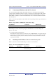
SuperH™ Family E10A-USB Emulator 1.4 Section 1 Connecting the Emulator with the User System Pin Assignments of the H-UDI Port Connector Figure 1.1 shows the pin assignments of the 14-pin H-UDI port connector. Note: Note that the pin number assignments of the H-UDI port connector shown on the following pages differ from those of the connector manufacturer. Pin No. Input/ Output*1 Signal 1 TCK 2 TRST# 3 TDO 4 N.C. 5 TMS 6 TDI 7 RES# 8 N.C.
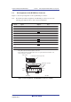
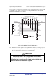
SuperH™ Family E10A-USB Emulator 1.5 1.5.1 Section 1 Connecting the Emulator with the User System Recommended Circuit between the H-UDI Port Connector and the MCU Recommended Circuit (14-Pin Type) Figure 1.2 shows a recommended circuit for connection between the H-UDI port connector (14 pins) and the MCU when the emulator is in use. Notes: 1. Do not connect anything to the N.C. pins of the H-UDI port connector. 2.
SuperH™ Family E10A-USB Emulator Section 1 Connecting the Emulator with the User System When the circuit is connected as shown in figure 1.2, the switches of the emulator are set as SW2 TM = 1 and SW3 = 1. For details, refer to section 3.8, Setting the DIP Switches, in the SuperH Family E10A-USB Emulator User’s Manual. Vcc = I/O power supply All pulled-up at 4.7 kΩ to 10 kΩ Vcc Vcc Vcc Vcc Vcc Vcc TCK 10 GND TRST# GND TDO N.C.
SuperH™ Family E10A-USB Emulator R20UT2188EJ0100 Rev. 1.
SuperH™ Family E10A-USB Emulator Section 2 Software Specifications when Using the Emulator Section 2 Software Specifications when Using the Emulator 2.1 Differences between the SH72A2, SH72A0, and the Emulator 1. When the emulator system is initiated, it initializes the general registers and part of the control registers as shown in table 2.1. The initial values of the MCU are undefined. Table 2.
SuperH™ Family E10A-USB Emulator Section 2 Software Specifications when Using the Emulator 5. Direct Memory Access Controller (DMAC) The DMAC operates even when the emulator is used. When a data transfer request is generated, the DMAC executes DMA transfer. 6. Memory Access during User Program Execution During execution of the user program, memory is accessed by the following two methods, as shown in table 2.2. Table 2.
SuperH™ Family E10A-USB Emulator Section 2 Software Specifications when Using the Emulator 10. Loading Sessions Information in [JTAG clock] of the [Configuration] dialog box cannot be recovered by loading sessions. Thus the TCK value will be as follows: ⎯ When HS0005KCU01H or HS0005KCU02H is used: TCK = 2.5 MHz 11. [IO] Window ⎯ Customization of the I/O-register definition file The internal I/O registers can be accessed from the [IO] window.
SuperH™ Family E10A-USB Emulator 2.2 2.2.1 Section 2 Software Specifications when Using the Emulator Specific Functions for the Emulator when Using the SH72A2 and SH72A0 Event Condition Functions The emulator is used to set event conditions for the following three functions: • Break of the user program • Internal trace • Start or end of performance measurement Table 2.5 lists the types of Event Condition. Table 2.
SuperH™ Family E10A-USB Emulator Section 2 Software Specifications when Using the Emulator Table 2.6 lists the combinations of conditions that can be set under Ch1 to Ch11. Table 2.
SuperH™ Family E10A-USB Emulator Section 2 Software Specifications when Using the Emulator (1) Sequential Setting Using the [Combination action (Sequential or PtoP)] dialog box specifies the sequential condition and the start or end of performance measurement. Table 2.7 Conditions to Be Set Classification Item Description [Ch1, 2, 3] list box Sets the sequential condition and the start or end of performance measurement using Event Conditions 1 to 3 and 11.
SuperH™ Family E10A-USB Emulator Section 2 Software Specifications when Using the Emulator Table 2.7 Conditions to Be Set (cont) Classification Item Description [Ch1, 2, 3] list box (cont) Ch1 to Ch2 PA Sets the performance measurement period during the time from the satisfaction of the condition set in Event Condition 1 (start condition) to the satisfaction of the condition set in Event Condition 2 (end condition).
SuperH™ Family E10A-USB Emulator Section 2 Software Specifications when Using the Emulator (2) Usage Example of Sequential Break Extension Setting A tutorial program provided for the product is used as an example. For the tutorial program, refer TM to section 6, Tutorial, in the SuperH Family E10A-USB Emulator User’s Manual. The conditions of Event Condition are set as follows: 1. Ch3 Breaks address H’00001088 when the condition [Only program fetched address after] is satisfied. 2.
SuperH™ Family E10A-USB Emulator Section 2 Software Specifications when Using the Emulator Notes: 1. If the Event condition is set for the slot in the delayed branch instruction by the program counter (after execution of the instruction), the condition is satisfied before executing the instruction in the branch destination (when a break has been set, it occurs before executing the instruction in the branch destination). 2.
SuperH™ Family E10A-USB Emulator 2.2.2 Section 2 Software Specifications when Using the Emulator Trace Functions The emulator supports the trace functions listed in table 2.8. Table 2.8 Trace Functions Function Internal Trace Branch trace Supported Memory access trace Supported Software trace Not supported (1) Internal Trace Function When [I-Trace] is selected for [Trace type] on the [Trace Mode] page of the [Acquisition] dialog box, the internal trace can be used. Figure 2.
SuperH™ Family E10A-USB Emulator Section 2 Software Specifications when Using the Emulator The following six items can be selected as the internal trace from [Type] of [I-Trace mode]. Table 2.9 Information on Acquiring the Internal Trace Item Acquisition Information [M-Bus & Branch] Acquires the data and branch information on the M-bus. • Data access (read/write) • PC-relative access • Branch information [I-Bus] Acquires the data on the I-bus.
SuperH™ Family E10A-USB Emulator Section 2 Software Specifications when Using the Emulator To restrict trace acquisition to access for only a specific address or specific function of a program, an Event Condition can be used. Typical examples are described below. • Example of halting a trace with a write access (M-bus) to H’FFF80000 by the user program as a condition (trace halt): Set the condition to be acquired on [I-Trace mode].
SuperH™ Family E10A-USB Emulator Section 2 Software Specifications when Using the Emulator • Point-to-point The trace-start condition is satisfied when the specified instruction has been fetched. Accordingly, if the trace-start condition has been set for the overrun-fetched instruction (an instruction that is not executed although it has been fetched at a branch or transition to an interrupt), tracing is started during overrun-fetching of the instruction.
SuperH™ Family E10A-USB Emulator Section 2 Software Specifications when Using the Emulator • Branch trace If breaks occur immediately after executing non-delayed branch and TRAPA instructions and generating a branch due to exception or interrupt, a trace for one branch will not be acquired immediately before such breaks. However, this does not affect on generation of breaks caused by a BREAKPOINT and a break before executing instructions of Event Condition.
SuperH™ Family E10A-USB Emulator 2.2.6 Section 2 Software Specifications when Using the Emulator Performance Measurement Function The emulator supports the performance measurement function. (1) Setting the Performance Measurement Conditions To set the performance measurement conditions, use the [Performance Analysis] dialog box and the PERFORMANCE_SET command.
SuperH™ Family E10A-USB Emulator Section 2 Software Specifications when Using the Emulator Regarding Errors in Measurement Errors in the results of the performance measurement function for numbers of cycles of execution are incurred immediately before the start of execution and immediately after a break. The errors differ according to the conditions that are in use. The procedure for evaluating the error is described below.
SuperH™ Family E10A-USB Emulator (b) Section 2 Software Specifications when Using the Emulator Measurement Item Items are measured with [Channel 1 to 4] in the [Performance Analysis] dialog box. Maximum four conditions can be specified at the same time. Table 2.13 Measurement Item Selected Name Option Disabled None Elapsed time AC (The number of execution cycles (Iφ).
SuperH™ Family E10A-USB Emulator (2) Section 2 Software Specifications when Using the Emulator Displaying the Measured Result The measured result is displayed in the [Performance Analysis] window or the PERFORMANCE_ANALYSIS command with hexadecimal (32 bits). Note: If a performance counter overflows as a result of measurement, “********” will be displayed.
SuperH™ Family E10A-USB Emulator Additional Document for User’s Manual Supplementary Information on Using the SH72A2 and SH72A0 Group Publication Date: Rev.1.
http://www.renesas.com SALES OFFICES Refer to "http://www.renesas.com/" for the latest and detailed information. Renesas Electronics America Inc. 2880 Scott Boulevard Santa Clara, CA 95050-2554, U.S.A. Tel: +1-408-588-6000, Fax: +1-408-588-6130 Renesas Electronics Canada Limited 1101 Nicholson Road, Newmarket, Ontario L3Y 9C3, Canada Tel: +1-905-898-5441, Fax: +1-905-898-3220 Renesas Electronics Europe Limited Dukes Meadow, Millboard Road, Bourne End, Buckinghamshire, SL8 5FH, U.
SuperH™ Family E10A-USB Emulator Additional Document for User’s Manual Supplementary Information on Using the SH72A2 and SH72A0 Group R20UT2188EJ0100