User’s Manual SuperH™ Family E10A-USB Emulator Additional Document for User’s Manual Supplementary Information on Using the SH7752 SuperH™ Family E10A-USB for SH7752 HS7752KCU01HE All information contained in these materials, including products and product specifications, represents information on the product at the time of publication and is subject to change by Renesas Electronics Corporation without notice.
Notice 1. Descriptions of circuits, software and other related information in this document are provided only to illustrate the operation of semiconductor products and application examples. You are fully responsible for the incorporation of these circuits, software, and information in the design of your equipment. Renesas Electronics assumes no responsibility for any losses incurred by you or third parties arising from the use of these circuits, software, or information. 2.
Regulatory Compliance Notices European Union regulatory notices This product complies with the following EU Directives. (These directives are only valid in the European Union.) CE Certifications: • Electromagnetic Compatibility (EMC) Directive 2004/108/EC EN 55022 Class A WARNING: This is a Class A product. In a domestic environment this product may cause radio interference in which case the user may be required to take adequate measures.
Table of Contents Section 1 Connecting the Emulator with the User System .................................................................... 1 1.1 1.2 1.3 1.4 1.5 Components of the Emulator .................................................................................................................................... 1 Connecting the Emulator with the User System .......................................................................................................
SuperH™ Family E10A-USB Emulator Section 1 Connecting the Emulator with the User System Section 1 Connecting the Emulator with the User System 1.1 Components of the Emulator The emulator supports the SH7752. Table 1.1 lists the components of the emulator. Table 1.1 Components of the Emulator Classification Component Hardware Emulator box Appearance Quantity 1 Remarks HS0005KCU01H: Depth: 65.0 mm, Width: 97.0 mm, Height: 20.0 mm, Mass: 72.9 g or HS0005KCU02H: Depth: 65.0 mm, Width: 97.
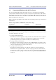
SuperH™ Family E10A-USB Emulator 1.2 Section 1 Connecting the Emulator with the User System Connecting the Emulator with the User System To connect the E10A-USB emulator (hereinafter referred to as the emulator), the H-UDI port connector must be installed on the user system to connect the user system interface cable. When designing the user system, refer to an example of recommended connection between the connector and the MPU shown in this manual.
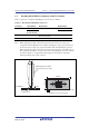
SuperH™ Family E10A-USB Emulator 1.3 Section 1 Connecting the Emulator with the User System Installing the H-UDI Port Connector on the User System Table 1.3 shows the recommended H-UDI port connectors for the emulator. Table 1.3 Recommended H-UDI Port Connectors Connector Type Number Manufacturer Specifications 36-pin connector DX10M-36S Hirose Electric Co., Ltd. Screw type Lock-pin type DX10M-36SE, DX10G1M-36SE 14-pin connector 2514-6002 Minnesota Mining & Manufacturing Ltd.
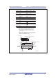
SuperH™ Family E10A-USB Emulator 1.4 Section 1 Connecting the Emulator with the User System Pin Assignments of the H-UDI Port Connector Figures 1.2 through 1.4 show the pin assignments of the 36-pin, 14-pin, and 38-pin H-UDI port connectors, respectively. Note: Note that the pin number assignments of the H-UDI port connector shown on the following pages differ from those of the connector manufacturer. Pin No.
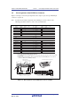
SuperH™ Family E10A-USB Emulator Section 1 Connecting the Emulator with the User System Signal Input/ Output*1 1 TCK Input C18 2 TRST# Input B17 3 TDO Output C17 4 ASEBRK# Input/ K5 Pin No. *2 *2 SH7752 Pin No. / BRKACK output 5 TMS Input B18 6 TDI Input D18 7 RESET# Output F1 8 N.C. 9 (GND) 11 UVCC 10, 12, GND *2 Note User reset *4 Output and 13 14 GND *3 Output Notes: 1. Input to or output from the user system. 2.
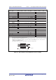
SuperH™ Family E10A-USB Emulator Pin No. Signal 1 N.C. 2 N.C. Section 1 SH7752 Pin No. Input/ Output*1 Note *4 3 MPMD (GND) 4 N.C. 5 UCON# (GND) *3 6 AUDCK 7 N.C. 8 ASEBRK#/ BRKACK *2 Output H3 Input/ Output Output K5 Connecting the Emulator with the User System Pin No. Signal 20 N.C. 21 TRST# *2 22 N.C. 23 N.C. 24 AUDATA3 25 N.C. 26 AUDATA2 27 N.C. 9 RESET# *2 10 N.C. 11 TDO Output 12 UVCC_AUD Output 13 N.C. 32 AUDSYNC 14 UVCC Output 33 N.C.
SuperH™ Family E10A-USB Emulator 1.5 1.5.1 Section 1 Connecting the Emulator with the User System Recommended Circuit between the H-UDI Port Connector and the MPU Recommended Circuit (36-Pin Type) Figure 1.5 shows a recommended circuit for connection between the H-UDI and AUD port connectors (36 pins) and the MPU when the emulator is in use. Notes: 1. Do not connect anything to the N.C. pins of the H-UDI port connector. 2.
SuperH™ Family E10A-USB Emulator Section 1 Connecting the Emulator with the User System When the circuit is connected as shown in figure 1.5, the switches of the emulator are set as SW2 TM = 1 and SW3 = 1. For details, refer to section 3.8, Setting the DIP Switches, in the SuperH Family E10A-USB Emulator User’s Manual.
SuperH™ Family E10A-USB Emulator 1.5.2 Section 1 Connecting the Emulator with the User System Recommended Circuit (14-Pin Type) Figure 1.6 shows a recommended circuit for connection between the H-UDI port connector (14 pins) and the MPU when the emulator is in use. Notes: 1. Do not connect anything to the N.C. pins of the H-UDI port connector. 2. The MPMD pin must be 0 when the emulator is connected and 1 when the emulator is not connected, respectively.
SuperH™ Family E10A-USB Emulator Section 1 Connecting the Emulator with the User System When the circuit is connected as shown in figure 1.6, the switches of the emulator are set as SW2 TM = 1 and SW3 = 1. For details, refer to section 3.8, Setting the DIP Switches, in the SuperH Family E10A-USB Emulator User’s Manual.
SuperH™ Family E10A-USB Emulator 1.5.3 Section 1 Connecting the Emulator with the User System Recommended Circuit (38-Pin Type) Figure 1.7 shows a recommended circuit for connection between the H-UDI and AUD port connectors (38 pins) and the MPU when the emulator is in use. Notes: 1. Do not connect anything to the N.C. pins of the H-UDI port connector. 2. The MPMD pin must be 0 when the emulator is connected and 1 when the emulator is not connected, respectively.
SuperH™ Family E10A-USB Emulator Section 1 Connecting the Emulator with the User System When the circuit is connected as shown in figure 1.7, the switches of the emulator are set as SW2 TM = 1 and SW3 = 1. For details, refer to section 3.8, Setting the DIP Switches, in the SuperH Family E10A-USB Emulator User’s Manual. VCCQ = I/O power supply All pulled-up at 4.
SuperH™ Family E10A-USB Emulator Section 2 Software Specifications when Using the SH7752 Section 2 Software Specifications when Using the SH7752 2.1 Differences between the SH7752 and the Emulator 1. When the emulator system is initiated, it initializes the general registers and part of the control registers as shown in table 2.1. The initial values of the actual SH7752 registers are undefined. Table 2.
SuperH™ Family E10A-USB Emulator Section 2 Software Specifications when Using the SH7752 4. Reset Signals The SH7752 reset signals are only valid during emulation started with clicking the GO or STEP-type button. If these signals are enabled on the user system in command input wait state, they are not sent to the SH7752. Note: Do not break the user program when the PRESET# signal is being low and the WAIT control signal is being active. A TIMEOUT error will occur.
SuperH™ Family E10A-USB Emulator Section 2 Software Specifications when Using the SH7752 9. Port The AUD pins are multiplexed as shown in table 2.2. Table 2.2 Multiplexed Functions Function 1 Function 2 PTL1/RAC-DCD#/DCD0# AUDCK (AUD) PTL2/RAC-DSR#/DSR0# AUDSYNC (AUD) PTT7/PWMX7/MD2 AUDATA3 (AUD) PTT6/PWMX6 AUDATA2 (AUD) PTT5/PWMX5 AUDATA1 (AUD) PTT4/PWMX4 AUDATA0 (AUD) Note: Function 1 can be used when the AUD pins of the device are not connected to the emulator.
SuperH™ Family E10A-USB Emulator Section 2 Software Specifications when Using the SH7752 13. [IO] Window ⎯ Display and modification Do not change values of the User Break Controller because it is used by the emulator. The watchdog timer operates only when the user program is executed. Do not change the value of the frequency change register in the [IO] window or [Memory] window. The internal I/O registers can be accessed from the [IO] window.
SuperH™ Family E10A-USB Emulator 2.2 2.2.1 Section 2 Software Specifications when Using the SH7752 Specific Functions for the Emulator when Using the SH7752 Event Condition Functions The emulator is used to set 12 event conditions (Ch1 to Ch12) and the software trace. Table 2.3 lists the conditions of Event Condition. Table 2.
SuperH™ Family E10A-USB Emulator Section 2 Software Specifications when Using the SH7752 Table 2.
SuperH™ Family E10A-USB Emulator Section 2 Software Specifications when Using the SH7752 Table 2.
SuperH™ Family E10A-USB Emulator Section 2 Software Specifications when Using the SH7752 Sequential Setting: In the emulator, sequential setting of an Event Condition is enabled. Table 2.5 Sequential Event Conditions Type Event Condition Description [CPU 2 Channel Ch2 -> 1 Sequential Sequential Event] Page Halts a program when a condition is satisfied in the order of Event Condition 2, 1. An event condition must be set for Ch2 and Ch1.
SuperH™ Family E10A-USB Emulator Section 2 Software Specifications when Using the SH7752 Sequential Break Extension Setting: Figure 2.1 [CPU Sequential Extend] Page (a) Indicates the channel name for setting conditions. (b) Selects a condition that is satisfied before the channel which sets up conditions. When a channel name is selected, it is required that the condition of the channel selected here must have already been satisfied. When [CPU Match flag] is selected, the CPU match flag must be set.
SuperH™ Family E10A-USB Emulator Section 2 Software Specifications when Using the SH7752 Usage Example of Sequential Break Extension Setting: A tutorial program provided for the product is used as an example. For the tutorial program, refer to section 6, Tutorial, in the TM SuperH Family E10A-USB Emulator User’s Manual. The conditions of Event Condition are set as follows: 1. Ch1 Breaks address H’00001068 when the condition [Prefetch address break after executing] is satisfied. 2.
SuperH™ Family E10A-USB Emulator 2.2.2 Section 2 Software Specifications when Using the SH7752 Trace Functions The emulator supports the trace functions listed in table 2.6. Table 2.6 Trace Functions Function Internal Trace AUD Trace Memory Output Trace Branch trace Supported (eight branches) Supported Supported Range memory access trace Supported (eight events) Supported Supported Software trace Supported (eight events) Supported Supported Table 2.
SuperH™ Family E10A-USB Emulator Section 2 Software Specifications when Using the SH7752 Branch Trace Functions: The branch source and destination addresses, their source lines, branch types, and types of accessed bus masters are displayed. [Setting Method] Select the check box in the [Branch] group box in the [Branch trace] page of the [Branch trace] dialog box that opens by double-clicking on the Ch12 (Branch) column of the [Eventpoint] window. The branch condition to be acquired can be set. Figure 2.
SuperH™ Family E10A-USB Emulator Section 2 Software Specifications when Using the SH7752 Range Memory Access Trace Functions: The memory access within the specified range is acquired by a trace. The read cycle, write cycle, or read/write cycle can be selected as the bus type, ASID value, or bus cycle for trace acquisition. [Setting Method] (i) To open the [Event condition 5] or [Event condition 6] dialog box, double-click on the Ch5 (OA) or Ch6 (OA) column of the [Eventpoint] window.
SuperH™ Family E10A-USB Emulator Section 2 Software Specifications when Using the SH7752 (iii) Open the [ASID] page, remove the check mark of the [Don’t care] check box, and enter the ASID value to be set. When the ASID value is not set as a condition, do not remove the check mark of the [Don’t care] check box. (iv) Open the [Bus state] page and specify the bus type and bus cycle that are to be set. Figure 2.
SuperH™ Family E10A-USB Emulator Section 2 Software Specifications when Using the SH7752 Software Trace Function: Note: This function can be supported with SHC/C++ compiler (manufactured by Renesas Electronics Corporation; including OEM and bundle products) V6.0 or later. However, SHC/C++ compiler (including OEM and bundle products) V8.0 or later is needed when instructions other than those compatible with SH4 are output.
SuperH™ Family E10A-USB Emulator Section 2 Software Specifications when Using the SH7752 AUD Trace Functions: This function is operational when the AUD pin of the device is connected to the emulator. It is activated by selecting the [AUD trace] radio button in the [Trace type] group box of the [Trace mode] page. Set the trace condition to be used. Table 2.8 shows the AUD trace acquisition mode that can be set in each trace function. Table 2.
SuperH™ Family E10A-USB Emulator Section 2 Software Specifications when Using the SH7752 To set the AUD trace acquisition mode, click the [Trace] window with the right mouse button and select [Setting] from the pop-up menu to display the [Acquisition] dialog box. The AUD trace acquisition mode can be set in the [Trace mode1], [Trace mode2], or [AUD mode] group box in the [Trace mode] page of the [Acquisition] dialog box. Figure 2.6 [Trace Mode] Page R20UT2163EJ0200 Rev. 2.
SuperH™ Family E10A-USB Emulator Section 2 Software Specifications when Using the SH7752 Notes on AUD Trace: 1. When the trace display is performed during user program execution, the mnemonics, operands, or source is not displayed. 2. The AUD branch trace function outputs the differences between newly output branch source addresses and previously output branch source addresses. The window trace function outputs the differences between newly output addresses and previously output addresses.
SuperH™ Family E10A-USB Emulator Section 2 Software Specifications when Using the SH7752 To set the memory-output trace acquisition mode, click the [Trace] window with the right mouse button and select [Setting] from the pop-up menu to display the [Acquisition] dialog box. The AUD trace acquisition mode can be set in the [Trace mode1] or [Trace mode2] group box in the [Trace mode] page of the [Acquisition] dialog box. Figure 2.7 [Trace Mode] Page Notes: 1.
SuperH™ Family E10A-USB Emulator 2.2.3 Section 2 Software Specifications when Using the SH7752 Notes on Using the JTAG (H-UDI) Clock (TCK) and AUD Clock (AUDCK) 1. Set the JTAG clock (TCK) frequency to lower than the frequency of the SH7752 peripheral module clock (CKP). 2. Set the AUD clock (AUDCK) frequency to 50 MHz or lower. If the frequency is higher than 50 MHz, the emulator will not operate normally. 3. The set value of the JTAG clock (TCK) is initialized by executing [Reset CPU] or [Reset Go].
SuperH™ Family E10A-USB Emulator Section 2 Software Specifications when Using the SH7752 8. When the [Virtual] option is selected in the [Memory area] group box in the [General] page of the [Configuration] dialog box, a BREAKPOINT is set to a virtual address. A BREAKPOINT is set after enabling the SH7752 MMU upon program execution. After setting, the MMU is returned to the original state. When an ASID value is specified, the BREAKPOINT is set to the virtual address corresponding to the ASID value.
SuperH™ Family E10A-USB Emulator 2.2.5 Section 2 Software Specifications when Using the SH7752 Notes on Setting the [Event Condition] Dialog Box and the BREAKCONDITION_ SET Command 1. When [Go to cursor], [Step In], [Step Over], or [Step Out] is selected, the settings of Event Condition 3 are disabled. 2. When an Event Condition is satisfied, emulation may stop after two or more instructions have been executed. 3.
SuperH™ Family E10A-USB Emulator Section 2 Software Specifications when Using the SH7752 Figure 2.8 [Performance Analysis] Dialog Box Note: For the command line syntax, refer to the online help. R20UT2163EJ0200 Rev. 2.
SuperH™ Family E10A-USB Emulator Section 2 Software Specifications when Using the SH7752 (a) Specifying the measurement start/end conditions Set the performance measurement conditions in the [Action] page after conditions have been set in the [Event Condition] dialog box that is opened by double-clicking Ch1 to Ch6 and Ch8 to Ch12 on the [Event Condition] sheet of the [Eventpoint] window. Notes: 1.
SuperH™ Family E10A-USB Emulator Section 2 Software Specifications when Using the SH7752 Figure 2.9 [Action] Page Note: PA1 or PA2 cannot be set for Ch8 and Ch9. (b) Measurement tolerance ⎯ The measured value includes tolerance. ⎯ Tolerance will be generated before or after a break. For details, see table 2.13. (c) Measurement items Items are measured in the [Performance Analysis] dialog box for each channel from Ch1 to Ch4. A maximum of four conditions can be specified at the same time. Table 2.
SuperH™ Family E10A-USB Emulator Section 2 Software Specifications when Using the SH7752 Table 2.11 Measurement Items Classification Type Measurement Item Option Note None Not measured. Elapsed cycles AC Except for power-on period; counted by the CPU clock. Cycles executed in privileged mode PM The number of privilegedmode cycles among the number of elapsed cycles. Cycles for asserting the SR.BL bit BL The number of cycles when the SR.BL bit = 1 among the number of elapsed cycles.
SuperH™ Family E10A-USB Emulator Section 2 Software Specifications when Using the SH7752 Classification Type Measurement Item Option Note TLB performance (cont) TLB (cont) Number of ITLB miss IM The number of ITLB misses for valid accesses (does not include UTLB hits or misses). Instruction bus performance Instruction Number of memory accesses for instruction fetch MIF The number of memory accesses by an instruction fetch. Accesses canceled by an instruction-fetch bus are not counted.
SuperH™ Family E10A-USB Emulator Section 2 Software Specifications when Using the SH7752 Classification Type Measurement Item Option Note Operand bus performance (cont) Access count (cont) Number of operand cache access (READ) CR The number of operandcache reads during memory access (read) of an operand. Number of operand cache access (WRITE) CW The number of operandcache reads during memory access (write) of an operand.
SuperH™ Family E10A-USB Emulator Section 2 Software Specifications when Using the SH7752 Classification Type Measurement Item Option Note Operand Bus performance (cont) Waited cycle (cont) Waited cycles for operand cache miss (READ) WCMR The number of waited cycles by an operand cache miss (read) (however, the number of waited cycles of cache fiII is included due to contention). Waited cycles for operand cache miss (WRITE) WCMW The number of waited cycles by an operand cache miss (write).
SuperH™ Family E10A-USB Emulator Section 2 Software Specifications when Using the SH7752 Table 2.12 shows the measurement items and methods that are mainly used. Table 2.
SuperH™ Family E10A-USB Emulator Section 2 Software Specifications when Using the SH7752 Each measurement condition is also counted when conditions in table 2.13 are generated. Table 2.13 Performance Measurement Conditions to be Counted Measurement Condition Notes No caching due to the settings of TLB cacheable bit Counted for accessing the cacheable area. Cache-on counting Accessing the non-cacheable area is counted less than the actual number of cycles and counts.
SuperH™ Family E10A-USB Emulator Additional Document for User’s Manual Supplementary Information on Using the SH7752 Publication Date: Rev. 2.
http://www.renesas.com SALES OFFICES Refer to "http://www.renesas.com/" for the latest and detailed information. Renesas Electronics America Inc. 2880 Scott Boulevard Santa Clara, CA 95050-2554, U.S.A. Tel: +1-408-588-6000, Fax: +1-408-588-6130 Renesas Electronics Canada Limited 1101 Nicholson Road, Newmarket, Ontario L3Y 9C3, Canada Tel: +1-905-898-5441, Fax: +1-905-898-3220 Renesas Electronics Europe Limited Dukes Meadow, Millboard Road, Bourne End, Buckinghamshire, SL8 5FH, U.
SuperH™ Family E10A-USB Emulator Additional Document for User’s Manual Supplementary Information on Using the SH7752 R20UT2163EJ0200