SuperH Family E10A Emulator Additional Document for User’s Manual SH7630 E10A HS7630KCM02HE Renesas Microcomputer Development Environment System SuperH Family / SH7600 Series Specific Guide for the SH7630 E10A Emulator Rev.1.00 2003.7.
Cautions Keep safety first in your circuit designs! 1. Renesas Technology Corporation puts the maximum effort into making semiconductor products better and more reliable, but there is always the possibility that trouble may occur with them. Trouble with semiconductors may lead to personal injury, fire or property damage.
Contents Section 1 Connecting the Emulator with the User System ................................1 1.1 1.2 1.3 1.4 1.5 Components of the Emulator ............................................................................................ 1 Connecting the E10A Emulator with the User System ..................................................... 4 Installing the H-UDI Port Connector on the User System ................................................ 5 Pin Arrangement of the H-UDI Port Connector................
ii
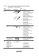
Section 1 Connecting the Emulator with the User System 1.1 Components of the Emulator The SH7630 E10A emulator supports the SH7630. Table 1.1 lists the components of the emulator.
Table 1.1 Components of the Emulator (HS7630KCM01H, HS7630KCM02H, HS7630KCI01H, or HS7630KCI02H) Classification Component Hardware Card emulator Appearance Quantity 1 PC PC Card (PCMCIA) Remarks HS7630KCM01H (PCMCIA: 14-pin type): Depth: 85.6 mm, Width: 54.0 mm, Height: 5.0 mm, Mass: 27.0 g HS7630KCM02H (PCMCIA: 36-pin type): Depth: 85.6 mm, Width: 54.0 mm, Height: 5.0 mm, Mass: 28.0 g or HS7630KCI01H (PCI: 14-pin type): Depth: 122.0 mm, Width: 96.0 mm, Mass: 80.
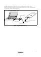
For EMI countermeasure, use the ferrite core by connecting the user interface cable. When the user interface cable is connected with the emulator or user system, connect the ferrite core in the user system as shown in figure 1.1. Host computer (PC with PC card slot) User system E10A emulator PC PC Card User system connector Ferrite core PC card slot User interface cable Figure 1.
1.2 Connecting the E10A Emulator with the User System To connect the E10A emulator (hereinafter referred to as the emulator), the H-UDI port connector must be installed on the user system to connect the user system interface cable. When designing the user system, refer to the recommended circuit between the H-UDI port connector and the MCU. In addition, read the E10A emulator user's manual and hardware manual for the related device. Table 1.
1.3 Installing the H-UDI Port Connector on the User System Table 1.3 shows the recommended H-UDI port connectors for the emulator. Table 1.3 Recommended H-UDI Port Connectors Connector Type Number Manufacturer Specifications 36-pin connector DX10M-36S Hirose Electric Co., Ltd. Screw type Lock-pin type DX10M-36SE, DX10G1M-36SE 14-pin connector 2514-6002 Minnesota Mining & Manufacturing Ltd.
Pin No. Signal Input/ SH7630 Output *1 Pin No. Note Pin No.
Pin No. Signal Input/ Output* 1 SH7630 Pin No. 1 TCK Input 27 2* 2 /TRST Input 24 3 TDO Output 25 4*2 /ASEBRKAK Output 7 5 TMS Input 28 6 TDI Input 26 7* 2 /RESETP Output 141 11 Not Note Pulled-up connected 8 to 10 GND 12 to 13 14* 3 GND Output Notes: 1. Input to or output from the user system. 2. The slash (/) means that the signal is active-low. 3. The emulator monitors the GND signal of the user system and detects whether the user system is connected or not.
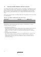
1.5 Recommended Circuit between the H-UDI Port Connector and the MPU 1.5.1 Recommended Circuit (36-Pin Type) Figure 1.4 shows a recommended circuit between the H-UDI port connector (36 pins) and the MPU. Notes: 1. Do not connect anything to the N.C. pin of the H-UDI port connector. 2. The processing of the /ASEMD0 pin differs depending on whether the emulator is used or not. As the emulator does not control this pin, it must be controlled by a switch on the board.
VccQ (3.3 V) VccQ (3.3 V) H-UDI port connector (36-pin type) 2 4 6 8 10 12 14 16 18 20 22 24 26 28 30 32 34 36 GND AUDCK GND AUDATA0 GND AUDATA1 GND AUDATA2 GND AUDATA3 GND AUDSYNC GND N.C. GND N.C. GND TCK GND TMS GND TRST GND TDI GND TDO GND ASEBRKAK GND NC GND RESET GND GND GND N.C. 4.7 kΩ SH7630 4.
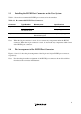
1.5.2 Recommended Circuit (14-Pin Type) Figure 1.5 shows a recommended circuit between the H-UDI port connector and the MPU. Notes: 1. 10 Do not connect anything to the N.C. pin of the H-UDI port connector. 2. The processing of the /ASEMD0 pin differs depending on whether the emulator is used or not. As the emulator does not control this pin, it must be controlled by a switch on the board.
VccQ (3.3 V) H-UDI port connector (14-pin type) 8 9 GND GND 10 GND TCK TRST 13 GND GND 14 GND 4.7 kΩ 1 TRST TDO TDO TMS TDI RESET SH7630 TCK 2 3 ASEBRKAK 12 4.7 kΩ VccQ (3.3 V) 4 ASEBRKAK 5 TMS 6 TDI 7 RESETP 11 NC Reset signal 1 kΩ ASEMD0 Figure 1.
12
Section 2 Specifications of the SH7630 E10A Emulator’s Software 2.1 Differences between the SH7630 and the Emulator • When the emulator system is initiated, it initializes the general registers and part of the control registers as shown in table 2.1. The initial values of the actual SH7630 registers are undefined. Table 2.
• Reset Signals The SH7630 reset signals are only valid during emulation started with clicking the GO or STEPtype button. If these signals are input from the user system in command input wait state, they are not sent to the SH7630. Note: Do not break the user program when the /RESETP and /WAIT signals are being low. A TIMEOUT error will occur. If the /WAIT signal is fixed to low during break, a TIMEOUT error will occur at memory access.
• UBC When [User] is specified in the [UBC mode] list box in the [Configuration] dialog box, the UBC can be used in the user program. Do not use the UBC in the user program as it is used by the E10A emulator when [EML] is specified in the [UBC mode] list box in the [Configuration] dialog box. • Loading Sessions Information in [JTAG clock] of the [Configuration] dialog box cannot be recovered by loading sessions. Thus the TCK value will be as follows: When HS7630KCI01H or HS7630KCI02H is used: TCK = 4.
• Illegal Instructions If illegal instructions are executed by STEP-type commands, the emulator cannot go to the next program counter. 2.2 Specific Functions for the SH7630 E10A Emulator The SH7630 E10A emulator does not support the following function: • MMU-related functions (The SH7630 does not mount the MMU.
Table 2.4 Types of Break Conditions Break Condition Type Description Address bus condition (Address) Breaks when the SH7630 address bus value or the program counter value matches the specified value. Data bus condition (Data) Breaks when the SH7630 data bus value matches the specified value. Byte, word, or longword can be specified as the access data size.
Table 2.5 lists the combinations of conditions that can be set under Break Condition 1, 2, 3. Table 2.5 Dialog Boxes for Setting Break Conditions Type Dialog Box Address Bus Condition (Address) Data Bus Condition (Data) Bus State Condition (Bus Status) Count Condition (Count) Internal I/O Break [Break Condition 1] dialog box O O O O X [Break Condition 2] dialog box O X O X X [Break Condition 3] dialog box X X X X O Note: O: Can be set in the dialog box.
AUD Trace Functions: This function is operational when the AUD pin of the device is connected to the emulator. Table 2.8 shows the AUD trace acquisition mode that can be set in each trace function. Table 2.8 AUD Trace Acquisition Mode Type Mode Description Continuous trace occurs Realtime trace When the next branch occurs while the trace information is being output, the trace information being output is output but the next trace information is not output.
To set the AUD trace acquisition mode, click the [Trace] window with the right mouse button and select [Setting] from the pop-up menu to display the [Acquisition] dialog box. The AUD trace acquisition mode can be set in the [AUD mode1] or [AUD mode2] group box in the [Trace mode] page of the [Acquisition] dialog box. Figure 2.1 [Trace mode] Page When the AUD trace function is used, select the [AUD function] radio button in the [Trace type] group box of the [Trace mode] page.
(a) Branch Trace Function The branch source and destination addresses and their source lines are displayed. Branch trace can be acquired by selecting the [Branch trace] check box in the [AUD function] group box of the [Trace mode] page. The branch type can be selected in the [AUD Branch trace] page. Figure 2.2 [AUD Branch trace] Page (b) Window Trace Function Memory access in the specified range can be acquired by trace. Two memory ranges can be specified for channels A and B.
Figure 2.3 [Window trace] Page Note: When the [L-bus] or [I-bus] radio button is selected, the following bus cycles will be traced. L-bus: A bus cycle generated by the CPU is acquired. A bus cycle is also acquired when the cache has been hit. I-bus: A bus cycle generated by the CPU or DMA is acquired. A bus cycle is not acquired when the cache has been hit. The address information acquired by the I-bus is 28 bits and the upper 4 bits are displayed as ‘*’.
(c) Software Trace Function Note: This function can be supported with SHC compiler V7.0 and later. When a specific instruction is executed, the PC value at execution and the contents of one general register are acquired by trace. Describe the Trace(x) function (x is a variable name) to be compiled and linked beforehand. For details, refer to the SHC manual.
Internal Trace Function: This function is activated by selecting the [Internal trace] radio button in the [Trace type] group box of the [Trace mode] page. See figure 2.1, [Trace mode] Page. The internal trace functions are also activated by selecting each check box on the [Branch trace] page. Notes: 1. If an interrupt is generated at the program execution start or end, including a step execution, the emulator address may be acquired. In such a case, the following message will be displayed.
6. When a BREAKPOINT is set to the slot instruction of a delayed branch instruction, the PC value becomes an illegal value. Accordingly, do not set a BREAKPOINT to the slot instruction of a delayed branch instruction. 7. When a BREAKPOINT is set to the cacheable area, the cache block containing the BREAKPOINT address is filled immediately before and after user program execution. 8. Note on DSP repeat loop: A BREAKPOINT is equal to a branch instruction.
2.2.7 Notes on Setting the UBC_MODE Command In the [Configuration] window, if [User] is set while the [UBC mode] list box has been set, the STEP-type commands that use Break Condition 2 for implementation cannot be used. 2.2.8 Performance Measurement Function The SH7630 E10A emulator supports the performance measurement function. 1. Setting the performance measurement conditions To set the performance measurement conditions, use the [Performance Analysis] dialog box and the PERFORMANCE_SET command.
Figure 2.4 [Performance Analysis] Dialog Box Measurement range One of the following ranges can be specified. This depends on the item selected for [Mode] in the [Performance Analysis] dialog box. 1. From the start to the end of the user program execution (When Normal Break is selected for [Mode]) 2. From the satisfaction of the condition set in Break Condition 1 to the satisfaction of the condition set in Break Condition 2 (When Break condition 1->2 is selected for [Mode]) 3.
2. Step execution is not possible when Break condition 1->2 or Break condition 2->1 is selected for the PERFORMANCE_SET command or in [Mode] of the [Performance Analysis] dialog box. 3. When Break condition 1->2 or Break condition 2->1 is selected in [Mode] of the [Performance Analysis] dialog box, specify one or more items for measurement. When there is no item, the error message “Measurement item does not have specification. Please set up a measurement item.” will be displayed.
Table 2.10 Measurement Item Selected Name Option Disabled None Elapsed time AC Number of execution states VS Branch instruction counts BT Number of execution instructions I DSP-instruction execution counts DI (Devices incorporating the DSP function can only be measured.) Instruction/data conflict cycle MAC Other conflict cycles than instruction/data OC Exception/interrupt counts EA Data-TLB miss cycle MTS (Devices incorporating the MMU function can only be measured.
Table 2.
TM SuperH Family E10A Emulator Additional Document for User's Manual Specific Guide for the SH7630 E10A Emulator Publication Date: Rev.1.00, July 3, 2003 Published by: Sales Strategic Planning Div. Renesas Technology Corp. Edited by: Technical Documentation & Information Department Renesas Kodaira Semiconductor Co., Ltd. 2003 Renesas Technology Corp. All rights reserved. Printed in Japan.
SuperH Family E10A Emulator Additional Document for User’s Manual REJ10B0015-0100H