User’s Manual SuperH™ Family E10A-USB Emulator Additional Document for User’s Manual Supplementary Information on Using the SH7083, SH7084, SH7085, and SH7086 SuperH™ Family / SH7080 Series E10A-USB for SH7080 HS7080KCU01HE All information contained in these materials, including products and product specifications, represents information on the product at the time of publication and is subject to change by Renesas Electronics Corporation without notice.
Notice 1. Descriptions of circuits, software and other related information in this document are provided only to illustrate the operation of semiconductor products and application examples. You are fully responsible for the incorporation of these circuits, software, and information in the design of your equipment. Renesas Electronics assumes no responsibility for any losses incurred by you or third parties arising from the use of these circuits, software, or information. 2.
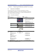
Regulatory Compliance Notices European Union regulatory notices This product complies with the following EU Directives. (These directives are only valid in the European Union.) CE Certifications: • Electromagnetic Compatibility (EMC) Directive 2004/108/EC EN 55022 Class A WARNING: This is a Class A product. In a domestic environment this product may cause radio interference in which case the user may be required to take adequate measures.
Table of Contents Section 1 1.1 1.2 1.3 1.4 1.5 Section 2 2.1 2.2 Connecting the Emulator with the User System ............................................................... 1 Components of the Emulator .................................................................................................................................... 1 Connecting the Emulator with the User System .......................................................................................................
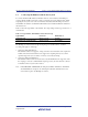
SuperH™ Family E10A-USB Emulator Section 1 Connecting the Emulator with the User System Section 1 Connecting the Emulator with the User System 1.1 Components of the Emulator The E10A-USB emulator supports the SuperH™ family SH7080 series: SH7083 (R5E70835R/R5F70834A/R5F70835A), SH7084 (R5E70845R/R5F70844A/R5F70845A), SH7085 (R5E70855R/R5F70854A/R5F70855A), and SH7086 (R5E70865R/R5F70865A). Table 1.1 lists the components of the emulator. Table 1.
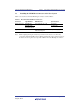
SuperH™ Family E10A-USB Emulator 1.2 Section 1 Connecting the Emulator with the User System Connecting the Emulator with the User System To connect the E10A-USB emulator (hereinafter referred to as the emulator), the H-UDI port connector must be installed on the user system to connect the user system interface cable. When designing the user system, refer to the recommended circuit between the H-UDI port connector and the MCU.
SuperH™ Family E10A-USB Emulator 1.3 Section 1 Connecting the Emulator with the User System Installing the H-UDI Port Connector on the User System Table 1.3 shows the recommended H-UDI port connectors for the emulator. Table 1.3 Recommended H-UDI Port Connectors Connector Type Number Manufacturer 36-pin connector DX10M-36S Hirose Electric Co., Ltd. DX10M-36SE, DX10G1M-36SE 14-pin connector 2514-6002 Specifications Screw type Lock-pin type Minnesota Mining & Manufacturing Ltd.
SuperH™ Family E10A-USB Emulator 1.4 Section 1 Connecting the Emulator with the User System Pin Assignments of the H-UDI Port Connector Figures 1.1 and 1.2 show the pin assignments of the 36-pin and 14-pin H-UDI port connectors, respectively. Note: Note that the pin number assignments of the H-UDI port connector shown on the following pages differ from those of the connector manufacturer. Pin No.
SuperH™ Family E10A-USB Emulator Section 1 Connecting the Emulator with the User System Signal Input/ Output*1 1 TCK Input 80 89 143 1 2 TRST# Input 77 86 139 174 3 TDO Output 79 88 142 176 4 ASEBRKAK# Input/ 100 102 144 2 Pin No. *2 *2 SH7083 SH7084 SH7085 SH7086 Pin No. Pin No. Pin No. Pin No. / ASEBRK# output 5 TMS Input 76 85 138 172 6 TDI Input 78 87 140 175 7 RES# Output 75 84 108 132 8 N.C.
SuperH™ Family E10A-USB Emulator Section 1 Connecting the Emulator with the User System 1.5 Recommended Circuit between the H-UDI Port Connector and the MCU 1.5.1 Recommended Circuit (36-Pin Type) Figure 1.3 shows a recommended circuit for connection between the H-UDI and AUD port connectors (36 pins) and the MCU when the emulator is in use. Notes: 1. Do not connect anything to the N.C. pins of the H-UDI port connector. 2.
SuperH™ Family E10A-USB Emulator Section 1 Connecting the Emulator with the User System When the circuit is connected as shown in figure 1.3, the switches of the emulator are set as SW2 = 1 and SW3 = 1. For details, refer to section 3.8, Setting the DIP Switches, in the SuperH™ Family E10A-USB Emulator User’s Manual. Vcc = I/O power supply Vcc Vcc Vcc All pulled-up at 4.
SuperH™ Family E10A-USB Emulator 1.5.2 Section 1 Connecting the Emulator with the User System Recommended Circuit (14-Pin Type) Figure 1.4 shows a recommended circuit for connection between the H-UDI port connector (14 pins) and the MCU when the emulator is in use. Notes: 1. Do not connect anything to the N.C. pins of the H-UDI port connector. 2. The ASEMD0# pin of the MCU must be 0 when the emulator is connected and 1 when the emulator is not connected, respectively.
SuperH™ Family E10A-USB Emulator Section 1 Connecting the Emulator with the User System When the circuit is connected as shown in figure 1.4, the switches of the emulator are set as SW2 = 1 and SW3 = 1. For details, refer to section 3.8, Setting the DIP Switches, in the SuperH™ Family E10A-USB Emulator User’s Manual. Vcc = I/O power supply Vcc Vcc All pulled-up at 4.
SuperH™ Family E10A-USB Emulator Section 1 Connecting the Emulator with the User System R20UT2159EJ0400 Rev. 4.
SuperH™ Family E10A-USB Emulator Section 2 Software Specifications when Using the SH7080 Series Section 2 Software Specifications when Using the SH7080 Series 2.1 Differences between the MCU and the Emulator 1. When the emulator system is initiated, it initializes the general registers and part of the control registers. The initial values of the MCU are undefined. When the emulator is initiated from the workspace, a value to be entered is saved in a session. Table 2.
SuperH™ Family E10A-USB Emulator Section 2 Software Specifications when Using the SH7080 Series 6. Memory Access during User Program Execution During execution of the user program, memory is accessed by the following two methods, as shown in table 2.2. Table 2.2 Memory Access during User Program Execution Method Description H-UDI read/write The stopping time of the user program is short because memory is accessed by the dedicated bus master. Short break This method is not used in this product.
SuperH™ Family E10A-USB Emulator Section 2 Software Specifications when Using the SH7080 Series 10. [IO] Window • Display and modification For each watchdog timer register, there are two registers to be separately used for write and read operations. Table 2.
SuperH™ Family E10A-USB Emulator Section 2 Software Specifications when Using the SH7080 Series 13. Multiplexing the Emulator Pins The emulator pin is assigned as shown in table 2.5. Table 2.
SuperH™ Family E10A-USB Emulator Section 2 Software Specifications when Using the SH7080 Series Table 2.
SuperH™ Family E10A-USB Emulator Section 2 Software Specifications when Using the SH7080 Series Table 2.
SuperH™ Family E10A-USB Emulator Section 2 Software Specifications when Using the SH7080 Series 2.2 Specific Functions for the Emulator when Using the SH7080 Series 2.2.1 Event Condition Functions The emulator is used to set event conditions for the following three functions: • Break of the user program • Internal trace • Start or end of performance measurement Table 2.6 lists the types of Event Condition. Table 2.
SuperH™ Family E10A-USB Emulator Section 2 Software Specifications when Using the SH7080 Series Table 2.7 lists the combinations of conditions that can be set under Ch1 to Ch10. Table 2.
SuperH™ Family E10A-USB Emulator Section 2 Software Specifications when Using the SH7080 Series Sequential Setting: Use the [Combination action (Sequential or PtoP)] dialog box to specify a sequential condition or the start or end of performance measurement. Table 2.8 Conditions to Be Set Classification Item [Ch1, 2, 3] list box Sets the sequential condition and the start or end of performance measurement using Event Conditions 1 to 3.
SuperH™ Family E10A-USB Emulator Section 2 Software Specifications when Using the SH7080 Series Usage Example of Sequential Break Extension Setting: A tutorial program provided for the product is used as an example. For the tutorial program, refer to section 6, Tutorial, in the SuperH™ Family E10A-USB Emulator User’s Manual. The conditions of Event Condition are set as follows: 1. Ch3 Breaks address H’00001068 when the condition [Only program fetched address after] is satisfied. 2.
SuperH™ Family E10A-USB Emulator Section 2 Software Specifications when Using the SH7080 Series Notes: 1. If the Event condition is set for the slot in the delayed branch instruction by the program counter (after execution of the instruction), the condition is satisfied before executing the instruction in the branch destination (when a break has been set, it occurs before executing the instruction in the branch destination). 2.
SuperH™ Family E10A-USB Emulator 2.2.2 Section 2 Software Specifications when Using the SH7080 Series Trace Functions The emulator supports the trace functions listed in table 2.9. The trace functions in table 2.9 are available for using the MCUs R5E70835R/R5E70845R/ R5E70855R/R5E70865R. Table 2.9 Trace Functions Function Internal Trace Branch trace Supported AUD Trace Supported Memory access trace Supported Supported Software trace Not supported Supported Table 2.
SuperH™ Family E10A-USB Emulator Section 2 Software Specifications when Using the SH7080 Series Internal Trace Function: When [I-Trace] is selected for [Trace type] on the [Trace Mode] page of the [Acquisition] dialog box, the internal trace can be used. Figure 2.2 [Acquisition] Dialog Box (Internal Trace Function) R20UT2159EJ0400 Rev. 4.
SuperH™ Family E10A-USB Emulator Section 2 Software Specifications when Using the SH7080 Series The following three items can be selected as the internal trace from [Type] of [I-Trace mode]. Table 2.11 Information on Acquiring the Internal Trace Item Acquisition Information [L-Bus & Branch] Acquires the data and branch information on the L-bus. • Data access (read/write) • Branch information • Instruction fetch [I-Bus] Acquires the data on the I-bus.
SuperH™ Family E10A-USB Emulator Section 2 Software Specifications when Using the SH7080 Series To restrict trace acquisition to access for only a specific address or specific function of a program, an Event Condition can be used. Typical examples are described below. • Example of halting a trace with a write access (L-bus) to H’FFFF8000 by the user program as a condition (trace halt): Set the condition to be acquired on [I-Trace mode].
SuperH™ Family E10A-USB Emulator Section 2 Software Specifications when Using the SH7080 Series Notes on Internal Trace: • Timestamp The timestamp is twice the crystal oscillator or the external clock that is connected to or input to the target MCU. Table 2.13 shows the timing for acquiring the timestamp. Table 2.
SuperH™ Family E10A-USB Emulator Section 2 Software Specifications when Using the SH7080 Series • Displaying a trace If a trace is displayed during execution of the program, execution will be suspended to acquire the trace information. (The number of clocks to be suspended during execution of the program is a maximum of about 16384 peripheral clocks (Pφ) + 12310 bus clocks (Bφ). If the peripheral clock (Pφ) is 10.0 MHz and the bus clock (Bφ) is 10.0 MHz, the program will be suspended for 2.87 ms.
SuperH™ Family E10A-USB Emulator Section 2 Software Specifications when Using the SH7080 Series AUD Trace Functions: This function is operational when the AUD pin of the device is connected to the emulator. Table 2.14 shows the AUD trace acquisition mode that can be set in each trace function. Table 2.
SuperH™ Family E10A-USB Emulator Section 2 Software Specifications when Using the SH7080 Series Figure 2.3 [Trace mode] Page When the AUD trace function is used, select the [AUD function] radio button in the [Trace type] group box of the [Trace mode] page. R20UT2159EJ0400 Rev. 4.
SuperH™ Family E10A-USB Emulator Section 2 Software Specifications when Using the SH7080 Series (a) Branch Trace Function The branch source and destination addresses and their source lines are displayed. Branch trace can be acquired by selecting the [Branch trace] check box in the [AUD function] group box of the [Trace mode] page. The branch type can be selected in the [AUD Branch trace] page. Figure 2.4 [AUD Branch trace] Page R20UT2159EJ0400 Rev. 4.
SuperH™ Family E10A-USB Emulator Section 2 Software Specifications when Using the SH7080 Series (b) Window Trace Function Memory access in the specified range can be acquired by trace. Two memory ranges can be specified for channels A and B. The read, write, or read/write cycle can be selected as the bus cycle for trace acquisition. [Setting Method] (i) Select the [Channel A] and [Channel B] check boxes in the [AUD function] group box of the [Trace mode] page. Each channel will become valid.
SuperH™ Family E10A-USB Emulator Section 2 Software Specifications when Using the SH7080 Series (c) Software Trace Function Note: This function can be supported with SHC/C++ compiler (manufactured by Renesas Electronics Corp.; including OEM and bundle products) V7.0 or later. When a specific instruction is executed, the PC value at execution and the contents of one general register are acquired by trace. Describe the Trace(x) function (x is a variable name) to be compiled and linked beforehand.
SuperH™ Family E10A-USB Emulator 2.2.3 Section 2 Software Specifications when Using the SH7080 Series Notes on Using the JTAG (H-UDI) Clock (TCK) 1. Set the JTAG clock (TCK) frequency to 1/4 or lower than the frequency of the peripheral clock (Pφ) and to 2 MHz or more. 2. The initial value of the JTAG clock (TCK) is 2.5 MHz. 3. A value to be set for the JTAG clock (TCK) is initialized after executing [Reset CPU] or [Reset Go]. Thus the TCK value will be 2.5 MHz. 2.2.
SuperH™ Family E10A-USB Emulator 2.2.6 Section 2 Software Specifications when Using the SH7080 Series Performance Measurement Function The emulator supports the performance measurement function. 1. Setting the performance measurement conditions To set the performance measurement conditions, use the [Performance Analysis] dialog box and the PERFORMANCE_SET command.
SuperH™ Family E10A-USB Emulator Section 2 Software Specifications when Using the SH7080 Series For measurement tolerance, • The measured value includes tolerance. • Tolerance will be generated before or after a break. Note: When [Ch2 to Ch1 PA] or [Ch1 to Ch2 PA] is selected, to execute the user program, specify conditions set in Event Condition 2 and Event Condition 1 and one or more items for performance measurement.
SuperH™ Family E10A-USB Emulator Section 2 Software Specifications when Using the SH7080 Series 2. Displaying the measured result The measured result is displayed in the [Performance Analysis] window or the PERFORMANCE_ANALYSIS command with hexadecimal (32 bits). Note: If a performance counter overflows as a result of measurement, “********” will be displayed. 3.
SuperH™ Family E10A-USB Emulator Additional Document for User’s Manual Supplementary Information on Using the SH7083, SH7084, SH7085, and SH7086 Publication Date: Rev. 4.
http://www.renesas.com SALES OFFICES Refer to "http://www.renesas.com/" for the latest and detailed information. Renesas Electronics America Inc. 2880 Scott Boulevard Santa Clara, CA 95050-2554, U.S.A. Tel: +1-408-588-6000, Fax: +1-408-588-6130 Renesas Electronics Canada Limited 1101 Nicholson Road, Newmarket, Ontario L3Y 9C3, Canada Tel: +1-905-898-5441, Fax: +1-905-898-3220 Renesas Electronics Europe Limited Dukes Meadow, Millboard Road, Bourne End, Buckinghamshire, SL8 5FH, U.
SuperH™ Family E10A-USB Emulator Additional Document for User’s Manual Supplementary Information on Using the SH7083, SH7084, SH7085, and SH7086 R20UT2159EJ0400