To our customers, Old Company Name in Catalogs and Other Documents On April 1st, 2010, NEC Electronics Corporation merged with Renesas Technology Corporation, and Renesas Electronics Corporation took over all the business of both companies. Therefore, although the old company name remains in this document, it is a valid Renesas Electronics document. We appreciate your understanding. Renesas Electronics website: http://www.renesas.
Notice 1. 2. 3. 4. 5. 6. 7. All information included in this document is current as of the date this document is issued. Such information, however, is subject to change without any prior notice. Before purchasing or using any Renesas Electronics products listed herein, please confirm the latest product information with a Renesas Electronics sales office.
User’s Manual SuperH™ Family E10A-USB Emulator Additional Document for User’s Manual Supplementary Information on Using the SH7146 and SH7149 Renesas Microcomputer Development Environment System SuperH™ Family / SH7146 Series E10A-USB for SH7146 HS7146KCU01HE Rev.4.00 2007.
Notes regarding these materials 1. This document is provided for reference purposes only so that Renesas customers may select the appropriate Renesas products for their use. Renesas neither makes warranties or representations with respect to the accuracy or completeness of the information contained in this document nor grants any license to any intellectual property rights or any other rights of Renesas or any third party with respect to the information in this document. 2.
Contents Section 1 Connecting the Emulator with the User System ................................1 1.1 1.2 1.3 1.4 1.5 Components of the Emulator ............................................................................................ 1 Connecting the Emulator with the User System ............................................................... 3 Installing the H-UDI Port Connector on the User System ................................................ 4 Pin Assignments of the H-UDI Port Connector ..........
ii
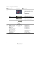
Section 1 Connecting the Emulator with the User System 1.1 Components of the Emulator The E10A-USB emulator supports the SuperH™ family SH7146 series and SH7146 (R5E71464R, R5F71464R, or R5F71464A)/SH7149 (R5E71494R‚ R5E71491R, R5F71494R, R5F71491R, or R5F71494A). Table 1.1 lists the components of the emulator.
Table 1.1 Components of the Emulator Classification Component Hardware Software Appearance Quantity Emulator box 1 User system interface cable User system interface cable 1 USB cable 1 1 Remarks HS0005KCU01H: Depth: 65.0 mm, Width: 97.0 mm, Height: 20.0 mm, Mass: 72.9 g or HS0005KCU02H: Depth: 65.0 mm, Width: 97.0 mm, Height: 20.0 mm, Mass: 73.7 g 14-pin type: Length: 20 cm, Mass: 33.1 g 36-pin type: Length: 20 cm, Mass: 49.2 g (only for HS0005KCU02H) Length: 150 cm, Mass: 50.
1.2 Connecting the Emulator with the User System To connect the E10A-USB emulator (hereinafter referred to as the emulator), the H-UDI port connector must be installed on the user system to connect the user system interface cable. When designing the user system, refer to the recommended circuit between the H-UDI port connector and the MCU. In addition, read the E10A-USB emulator user's manual and hardware manual for the related device. Table 1.
1.3 Installing the H-UDI Port Connector on the User System Table 1.3 shows the recommended H-UDI port connectors for the emulator. Table 1.3 Recommended H-UDI Port Connectors Connector Type Number Manufacturer Specifications 36-pin connector DX10M-36S Hirose Electric Co., Ltd. Screw type DX10M-36SE, DX10G1M-36SE 14-pin connector 2514-6002 Lock-pin type Minnesota Mining & Manufacturing Ltd.
SH7149 Pin No. SH7149 Pin No. Pin No. Signal 1 AUDCK 2 GND 3 AUDATA0 4 GND 5 AUDATA1 6 GND 7 AUDATA2 8 GND 9 AUDATA3 10 GND Input/ Output*1 LQFP100 Output 28 31 Output 34 37 Output Output Output 33 QFP100 Note 36 32 35 31 Pin No.
SH7149 Pin No. LQFP100 QFP100 Signal Input/ Output*1 1 TCK Input 7 3 6 2 _TRST Input 1 99 2 3 TDO Output 3 1 4 4 _ASEBRKAK Input/ 8 4 7 Pin No. *2 *2 SH7146 Pin No. / _ASEBRK output 5 TMS Input 2 100 3 6 TDI Input 5 2 5 7 _RES Output 52 64 67 8 N.C. 9 (GND) 11 UVCC 10, 12, GND *2 Note User reset *4 Output and 13 14 *3 GND Output Notes: 1. Input to or output from the user system. 2. The symbol (_) means that the signal is active-low. 3.
1.5 Recommended Circuit between the H-UDI Port Connector and the MCU 1.5.1 Recommended Circuit (36-Pin Type) Figure 1.3 shows a recommended circuit for connection between the H-UDI and AUD port connectors (36 pins) and the MCU when the emulator is in use. Notes: 1. Do not connect anything to the N.C. pins of the H-UDI port connector. 2. The _ASEMD0 pin must be 0 when the emulator is connected and 1 when the emulator is not connected, respectively.
When the circuit is connected as shown in figure 1.3, the switches of the emulator are set as SW2 TM = 1 and SW3 = 1. For details, refer to section 3.8, Setting the DIP Switches, in the SuperH Family E10A-USB Emulator User’s Manual. Vcc = I/O power supply Vcc Vcc Vcc All pulled-up at 4.7 kΩ or more H-UDI port connector (36-pin type) 2 4 6 8 10 12 14 16 18 20 22 24 GND AUDCK GND AUDATA0 GND AUDATA1 GND AUDATA2 GND AUDATA3 GND AUDSYNC GND N.C. GND N.C.
1.5.2 Recommended Circuit (14-Pin Type) Figure 1.4 shows a recommended circuit for connection between the H-UDI port connector (14 pins) and the MCU when the emulator is in use. Notes: 1. Do not connect anything to the N.C. pins of the H-UDI port connector. 2. The _ASEMD0 pin must be 0 when the emulator is connected and 1 when the emulator is not connected, respectively. (1) When the emulator is used: _ASEMD0 = 0 (2) When the emulator is not used: _ASEMD0 = 1 Figure 1.
When the circuit is connected as shown in figure 1.4, the switches of the emulator are set as SW2 TM = 1 and SW3 = 1. For details, refer to section 3.8, Setting the DIP Switches, in the SuperH Family E10A-USB Emulator User’s Manual. Vcc = I/O power supply Vcc Vcc All pulled-up at 4.7 kΩ or more Vcc Vcc Vcc Vcc Vcc Vcc H-UDI port connector (14-pin type) TCK 9 (GND) TRST Target MCU 1 TCK 2 TRST 3 TDO 4 ASEBRKAK /ASEBRK 5 12 GND TMS 6 13 TDI GND 7 14 GND RES 10 GND N.C.
Section 2 Software Specifications when Using the SH7146 Series 2.1 Differences between the MCU and the Emulator 1. When the emulator system is initiated, it initializes the general registers and part of the control registers. The initial values of the MCU are undefined. When the emulator is initiated from the workspace, a value to be entered is saved in a session. Table 2.
5. Direct Memory Access Controller (DMAC) When the MCU incorporates a DMAC, the DMAC operates even when the emulator is used. When a data transfer request is generated, the DMAC executes DMA transfer. When the MCU incorporates a DTC, the DTC operates even when the emulator is used. When a data transfer request is generated, the DTC executes DTC transfer. 6. Memory Access during User Program Execution During execution of the user program, memory is accessed by the following two methods, as shown in table 2.
9. Loading Sessions Information in [JTAG clock] of the [Configuration] dialog box cannot be recovered by loading sessions. Thus the TCK value will be as follows: • When HS0005KCU01H or HS0005KCU02H is used: TCK = 2.5 MHz 10. [IO] Window • Display and modification For each watchdog timer register, there are two registers to be separately used for write and read operations. Table 2.
13. Multiplexing the Emulator Pins The emulator pin is assigned as shown in table 2.5. Table 2.
When the multiplexed pins are used as the AUD functions, set the AUD pins to be used from [AUD pin select] of the [Configuration] dialog box. The multiplexed pins are fixed to be used as the AUD function.
2.2 Specific Functions for the Emulator when Using the SH7146 Series 2.2.1 Event Condition Functions The emulator is used to set event conditions for the following three functions: • Break of the user program • Internal trace • Start or end of performance measurement Table 2.6 lists the types of Event Condition. Table 2.
Table 2.7 lists the combinations of conditions that can be set under Ch1 to Ch10. Table 2.
Sequential Setting: Using the [Combination action (Sequential or PtoP)] dialog box specifies the sequential condition and the start or end of performance measurement. Table 2.8 Conditions to Be Set Classification Item [Ch1, 2, 3] list box Sets the sequential condition and the start or end of performance measurement using Event Conditions 1 to 3. [Ch4, 5] list box 18 Description Don’t care Sets no sequential condition or the start or end of performance measurement.
Notes: 1. If the start condition is satisfied after the end condition has been satisfied by measuring performance, performance measurement will be restarted. For the measurement result after a break, the measurement results during performance measurement are added. 2. If the start condition is satisfied after the end condition has been satisfied by the pointto-point of the internal trace, trace acquisition will be restarted. 3.
Figure 2.1 [Source] Window at Execution Halted (Sequential Break) If the sequential condition, performance measurement start/end, or point-to-point for the internal trace is set, conditions of Event Condition to be used will be disabled. Such conditions must be enabled from the popup menu by clicking the right mouse button on the [Event Condition] sheet. Notes: 1.
5. If the settings of the Event condition or the sequential conditions are changed during execution of the program, execution will be suspended. (The number of clocks to be suspended during execution of the program is a maximum of about 52 bus clocks (Bφ). If the bus clock (Bφ) is 10.0 MHz, the program will be suspended for 5.2 μs.) 6.
Internal Trace Function: When [I-Trace] is selected for [Trace type] on the [Trace Mode] page of the [Acquisition] dialog box, the internal trace can be used. Figure 2.
The following three items can be selected as the internal trace from [Type] of [I-Trace mode]. Table 2.11 Information on Acquiring the Internal Trace Item Acquisition Information [L-Bus & Branch] Acquires the data and branch information on the L-bus. • Data access (read/write) • Branch information • Instruction fetch [I-Bus] Acquires the data on the I-bus.
Using Event Condition restricts the condition; the following three items are set as the internal trace conditions. Table 2.12 Trace Conditions of the Internal Trace Item Acquisition Information Trace halt Acquires the internal trace until the Event Condition is satisfied. (The trace content is displayed in the [Trace] window after a trace has been halted. No break occurs in the user program.) Trace acquisition condition Acquires only the data access where the Event Condition is satisfied.
Set the address condition as H’2000 in the [Event Condition 4] dialog box. Set [Ch4,5] as [I-Trace Ch5 to Ch4 PtoP] in the [Combination action (Sequential or PtoP)] dialog box. When point-to-point and trace acquisition condition are set simultaneously, they are ANDed. Notes on Internal Trace: • Timestamp The timestamp is twice the crystal oscillator or the external clock that is connected to or input to the target MCU. Table 2.13 shows the timing for acquiring the timestamp. Table 2.
• Trace acquisition condition Do not set the trace end condition for the sleep instruction and the branch instruction according to which the delay slot becomes the sleep instruction. When [I-Bus, L-Bus & Branch] is selected and the trace acquisition condition is set for the Lbus and I-bus with Event Condition, set the L-bus condition and the I-bus condition for [Event Condition 1] and [Event Condition 2], respectively.
AUD Trace Functions: This function is operational when the AUD pin of the device is connected to the emulator. Table 2.14 shows the AUD trace acquisition mode that can be set in each trace function. Table 2.14 AUD Trace Acquisition Mode Type Mode Description Continuous trace occurs Realtime trace When the next branch occurs while the trace information is being output, all the information may not be output. The user program can be executed in realtime, but some trace information will be lost.
Figure 2.3 [Trace mode] Page When the AUD trace function is used, select the [AUD function] radio button in the [Trace type] group box of the [Trace mode] page.
(a) Branch Trace Function The branch source and destination addresses and their source lines are displayed. Branch trace can be acquired by selecting the [Branch trace] check box in the [AUD function] group box of the [Trace mode] page. The branch type can be selected in the [AUD Branch trace] page. Figure 2.
(b) Window Trace Function Memory access in the specified range can be acquired by trace. Two memory ranges can be specified for channels A and B. The read, write, or read/write cycle can be selected as the bus cycle for trace acquisition. [Setting Method] (i) Select the [Channel A] and [Channel B] check boxes in the [AUD function] group box of the [Trace mode] page. Each channel will become valid.
Note: When [L-Bus] or [I-Bus] is selected, the following bus cycles will be traced. • L-Bus: A bus cycle generated by the CPU is acquired. • I-Bus: A bus cycle generated by the CPU, DMA, or DTC is acquired. (Some MCUs will incorporate no DMAC or DTC.) (c) Software Trace Function Note: This function can be supported with SHC/C++ compiler (manufactured by Renesas Technology Corp.; including OEM and bundle products) V7.0 or later.
2.2.3 Notes on Using the JTAG (H-UDI) Clock (TCK) 1. Set the JTAG clock (TCK) frequency to 1/4 or lower than the frequency of the peripheral clock (Pφ) and to 2 MHz or more. 2. The initial value of the JTAG clock (TCK) is 2.5 MHz. 3. A value to be set for the JTAG clock (TCK) is initialized after executing [Reset CPU] or [Reset Go]. Thus the TCK value will be 2.5 MHz. 2.2.4 Notes on Setting the [Breakpoint] Dialog Box 1. When an odd address is set, the next lowest even address is used. 2.
2.2.6 Performance Measurement Function The emulator supports the performance measurement function. 1. Setting the performance measurement conditions To set the performance measurement conditions, use the [Performance Analysis] dialog box and the PERFORMANCE_SET command. When any line in the [Performance Analysis] window is clicked with the right mouse button, a popup menu is displayed and the [Performance Analysis] dialog box can be displayed by selecting [Setting].
Figure 2.6 [Performance Analysis] Dialog Box For measurement tolerance, • The measured value includes tolerance. • Tolerance will be generated before or after a break. Note: When [Ch2 to Ch1 PA] or [Ch1 to Ch2 PA] is selected, to execute the user program, specify conditions set in Event Condition 2 and Event Condition 1 and one or more items for performance measurement. (b) Measurement item Items are measured with [Channel 1 to 4] in the [Performance Analysis] dialog box.
Table 2.16 Measurement Item Selected Name Option Disabled None Elapsed time AC (The number of execution cycles (Iφ) is set as the measurement item.) Number of execution states VS Branch instruction counts BT Number of execution instructions I Exception/interrupt counts EA Interrupt counts INT URAM area access counts UN URAM area instruction access counts UIN URAM area data access counts UDN Note: Selected names are displayed for CONDITION in the [Performance Analysis] window.
3. Initializing the measured result To initialize the measured result, select [Initialize] from the popup menu in the [Performance Analysis] window or specify INIT with the PERFORMANCE_ANALYSIS command.
SuperH™ Family E10A-USB Emulator Additional Document for User's Manual Supplementary Information on Using the SH7146 and SH7149 Publication Date: Rev.1.00, February 28, 2006 Rev.4.00, August 23, 2007 Published by: Sales Strategic Planning Div. Renesas Technology Corp. Edited by: Customer Support Department Global Strategic Communication Div. Renesas Solutions Corp. ©2007. Renesas Technology Corp., All rights reserved. Printed in Japan.
Sales Strategic Planning Div. Nippon Bldg., 2-6-2, Ohte-machi, Chiyoda-ku, Tokyo 100-0004, Japan RENESAS SALES OFFICES http://www.renesas.com Refer to "http://www.renesas.com/en/network" for the latest and detailed information. Renesas Technology America, Inc. 450 Holger Way, San Jose, CA 95134-1368, U.S.A Tel: <1> (408) 382-7500, Fax: <1> (408) 382-7501 Renesas Technology Europe Limited Dukes Meadow, Millboard Road, Bourne End, Buckinghamshire, SL8 5FH, U.K.
SuperH™ Family E10A-USB Emulator Additional Document for User’s Manual Supplementary Information on Using the SH7146 and SH7149 1753, Shimonumabe, Nakahara-ku, Kawasaki-shi, Kanagawa 211-8668 Japan REJ10J1272-0400