
Installation guide


15
RS232 serial communications
4 RS232 serial communications
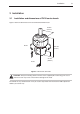
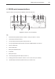
Figure 16 shows the rear panel of the RS232 version of the PHC10-2.
1
2 43 5 6 7 8 9
10
11 12
Figure 16 - PHC10-2 rear panel (RS232)
Key
1 Communications protocol selection, switches 1 to 10 (see tables 2, 3 and 4)
2 9-way D-type connector to HCU1
3 15-way D-type connector to probe head (see table 14)
4 25-way D-type RS232 communications connector to CMM computer (see table 1)
5 Version number label
6 Serial number label
7 Mains power ON/OFF switch
8 Fuseholder
9 Mains power input
10 9-way D-type plug for PICS output (see table 11)
11 Probing system format selection, switches 11 to 14 and 15 to 18 (see section 6)
12 7-pin DIN output connector to probe interface (see section 6.4.2)