
Installation guide

27
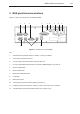
Probing system output (RS232 and IEEE)
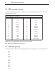
6.7 Summary of configuration switches
6.7.1 Summary of RS232 configuration switches
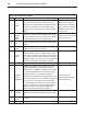
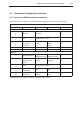
Table 16 presents a summary of the PHC10-2 RS232 configuration switch settings and functions.
Table 16 - Summary of RS232 configuration switches
Switch Function Up Down See section
Communications
1
2
3
Baud rate See table 2 4.2
4
5
None Default position = down
6*
7*
8*
Stop bit
CTS protocol
LF protocol
2 stop bits
CTS on
LF on
1 stop bit
CTS off
LF off
4.3.1
9 Command set Extended Basic 4.3
10 Probe reset time 2 (extended) 1 (standard) 6.5
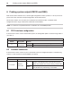
Interface
11 PICS configuration
PPOFF - active
during head index
PPOFF - inactive
during head index
6.1
12
HCU1 probe DAMP
and probe reset
buttons
Enabled Disabled 6.3
13
14
None Default position = down
15
16
Output
configuration
PICS DIN 6.4
17
18
Interface
connection
PICS or 7-pin DIN
operation
5-pin DIN operation
only
6.2
* Operational only when basic command set selected (switch 9 down).