
Installation guide

38
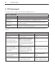
System interconnection diagrams
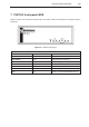
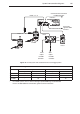
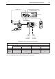
Figure 25 - PH10 system with multiwired probes and autochange
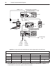
Table 24 - Switch settings
PICS configuration SSR configuration
Up Down Up Down
PHC10-2 11, 15, 16, 17, 18 10, 13, 14 - 10, 13, 14, 15, 16
PI 7-2 1, 3, 7 6 1, 3, 7 6
OPI 6 - 2,4 - 2,4
ACC2-2 9 A, B - 9, A, B
For these systems the use of the PICS signal probe DAMPing is recommended.
Refer to H-1000-5000 PIC’S installation guide for further information.
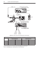
PH10M
PL5, 6, 12, 13
PLM6, 7, 8, 9
Communication connection
to CMM controller
PL38
HCU1
PHC10-2
PI 7-2
or
OPI 6
PL25
PICS
output
to CMM
controller
SSR
output
to CMM
controller
to autochange
rack
ACC2-2
Communication connection
to CMM controller