
User`s guide


26 PH10 Series User's Guide
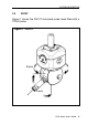
2.8 PHC10-2 probe head controller
continued
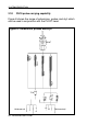
2.8.3 PHC10-2 rear panel
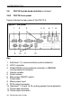
Figure 6 shows the rear panel of the PHC10-2.
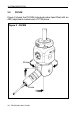
Figure 6 - rear panel
1 23 4 7658
91110 12
Key
1 Switches 1-10, communications protocol selection
2 HCU1 connector
3
Either
RS232 communications connector
or
IEEE488
communications connector
4 Version number
5 Serial number
6 Main power ON/OFF switch
7 Fuse holder
8 Mains power input
9 PICS output connector
10 Switches 11-14 and 15-18, probing system format selection
11 Probe head connector
12 Probe output connector
SYSTEM DESCRIPTION