
User manual

39
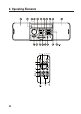
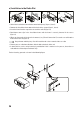
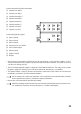
System connector B (speaker connection)
(1) Speaker rear right (+)
(2) Speaker rear right (-)
(3) Speaker front right (+)
(4) Speaker front right (-)
(5) Speaker front left (+)
(6) Speaker front left (-)
(7) Speaker rear left (+)
(8) Speaker rear left (-)
System plug A (power supply)
(1) (Not assigned)
(2) (Not assigned)
(3) (Not assigned)
(4) Permanent current +12/24 V
(5) Aerial control output
(6) (Not assigned)
(7) Ignition +12/24 V
(8) Weight
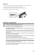
• The constant current terminal +12/24 V (4) must be connected to a cable that also supplies +12 V or
+24 V permanently when the ignition is o (terminal 30 of the on-board network). This terminal serves to
save the user settings, time, etc.
• The aerial control output (5) supplies a voltage of +12/24 V with the device on. This cable can be used for
the power supply of an electrical aerial and for the voltage for switching on a car amplifier.
• The ignition terminal +12/24 V (7) must be connected to a cable that is only live with +12 V or 24 V when
the ignition is on (terminal 15 of the on-board networks).
Do not connect this terminal to continuous current; otherwise the on-board battery could be
discharged when the vehicle is parked for a longer period of time.
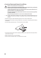
• Connect the earth connection (8) with the vehicle body.
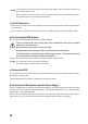
Adhesive techniques which become ever more common and painted metal parts impair the elec-
tric conductivity. Therefore, not every metal part is a suitable earthing point.