
User manual


25
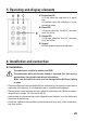
5. Operating and display elements
A) Red/yellow LED
Is lit red, when the code lock is in opera-
tion.
Is lit yellow, when the code lock is in pro-
gramming mode.
B) Green LED
Is lit green, when the “Lock Out” relay con-
tacts are active.
C) Orange LED
Is lit orange, when the “Aux Out” relay con-
tacts are active.
D) Keypad
For both programming and code entry.
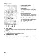
6. Installation and connection
6.1 Installation
The code lock is suitable for outdoor use (IP65).
The connection cables must not be kinked or squashed. This can result in
malfunctions, short circuits and defects in the device.
Make sure that cables or wires are not damaged when drilling or bolting
in place.
• Detach the housing cover on the back of the code lock by removing the screw on the
underside of the housing. A corresponding tool is supplied with the device.
• There are four round markings on the inside of the housing cover. Make correspon-
ding drill holes using a 3.5-4 mm metal drill bit.
• Another hole for the connection cable (depending on diameter) must be drilled into
the centre of the housing.
• Attach the code lock with suitable installation material to an even, vertical and vibra-
tion-free surface.