B450M S2H User's Manual Rev. 1001 For more product details, please visit GIGABYTE's website. To reduce the impacts on global warming, the packaging materials of this product are recyclable and reusable. GIGABYTE works with you to protect the environment.
Motherboard B450M S2H Motherboard B450M S2H Oct. 19, 2018 Oct. 19, 2018 Copyright © 2018 GIGA-BYTE TECHNOLOGY CO., LTD. All rights reserved. The trademarks mentioned in this manual are legally registered to their respective owners. Disclaimer Information in this manual is protected by copyright laws and is the property of GIGABYTE. Changes to the specifications and features in this manual may be made by GIGABYTE without prior notice.
Table of Contents B450M S2H Motherboard Layout.....................................................................................4 Chapter 1 Hardware Installation......................................................................................5 1-1 1-2 1-3 1-4 1-5 1-6 1-7 Installation Precautions..................................................................................... 5 Product Specifications.......................................................................................
B450M S2H Motherboard Layout CPU_FAN KB_MS ATX_12V Socket AM4 VGA DVI ATX HDMI R_USB30_1 R_USB30_2 SYS_FAN1 PCIEX1_1 M2A_SOCKET 60 80 B450M S2H PCIEX16 Realtek® GbE LAN 42 DDR4_1 M_BIOS LED_CPU AUDIO DDR4_2 USB_LAN 3 SATA3 SPDIF_O F_AUDIO Box Contents AMD B450 iTE® Super I/O TPM CI SPEAKER PCIEX1_2 F_USB2 55 B450M S2H motherboard 55 Motherboard driver disk 55 User's Manual SATA3 0 1 2 BAT CODEC CLR_CMOS F_USB30 F_USB1 F_PANEL 55 Two SATA cables 55 I/O Shield * The box
Chapter 1 1-1 Hardware Installation Installation Precautions The motherboard contains numerous delicate electronic circuits and components which can become damaged as a result of electrostatic discharge (ESD). Prior to installation, carefully read the user's manual and follow these procedures: •• Prior to installation, make sure the chassis is suitable for the motherboard. •• Prior to installation, do not remove or break motherboard S/N (Serial Number) sticker or warranty sticker provided by your dealer.
1-2 Product Specifications CPU AM4 Socket: - AMD Ryzen™ 2nd Generation processors - AMD Ryzen™ with Radeon™ Vega Graphics processors - AMD Ryzen™ 1st Generation processors (Go to GIGABYTE's website for the latest CPU support list.
Internal Connectors Back Panel Connectors 1 x 24-pin ATX main power connector 1 x 8-pin ATX 12V power connector 1 x CPU fan header 1 x system fan header 1 x M.2 Socket 3 connector 4 x SATA 6Gb/s connectors 1 x front panel header 1 x front panel audio header 1 x S/PDIF Out header 1 x CPU cooler LED strip/RGB LED strip header 1 x USB 3.1 Gen 1 header 2 x USB 2.0/1.
Unique Features Support for APP Center * Available applications in APP Center may vary by motherboard model. Supported functions of each application may also vary depending on motherboard specifications.
1-3 Installing the CPU Read the following guidelines before you begin to install the CPU: •• Make sure that the motherboard supports the CPU. (Go to GIGABYTE's website for the latest CPU support list.) •• Always turn off the computer and unplug the power cord from the power outlet before installing the CPU to prevent hardware damage. •• Locate the pin one of the CPU. The CPU cannot be inserted if oriented incorrectly. •• Apply an even and thin layer of thermal grease on the surface of the CPU.
1-5 Installing an Expansion Card Read the following guidelines before you begin to install an expansion card: •• Make sure the motherboard supports the expansion card. Carefully read the manual that came with your expansion card. •• Always turn off the computer and unplug the power cord from the power outlet before installing an expansion card to prevent hardware damage.
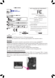
RJ-45 LAN Port The Gigabit Ethernet LAN port provides Internet connection at up to 1 Gbps data rate. The following describes the states of the LAN port LEDs. Connection/ Speed LED Connection/Speed LED: Activity LED LAN Port Activity LED: State Description State Description Orange 1 Gbps data rate Blinking Data transmission or receiving is occurring Green 100 Mbps data rate Off No data transmission or receiving is occurring Off 10 Mbps data rate USB 2.0/1.
1-7 Internal Connectors 3 1 2 4 16 6 17 5 7 9 13 12 14 15 8 11 10 1) ATX_12V 10) SPEAKER 2) ATX 11) F_USB30 3) CPU_FAN 12) F_USB1/F_USB2 4) SYS_FAN1 13) TPM 5) SATA3 0/1/2/3 14) CI 6) M2A_SOCKET 15) CLR_CMOS 7) SPDIF_O 16) LED_CPU 8) F_PANEL 17) BAT 9) F_AUDIO Read the following guidelines before connecting external devices: •• First make sure your devices are compliant with the connectors you wish to connect.
1/2) ATX_12V/ATX (2x4 12V Power Connector and 2x12 Main Power Connector) With the use of the power connector, the power supply can supply enough stable power to all the components on the motherboard. Before connecting the power connector, first make sure the power supply is turned off and all devices are properly installed. The power connector possesses a foolproof design. Connect the power supply cable to the power connector in the correct orientation.
3/4) CPU_FAN/SYS_FAN1 (Fan Headers) All fan headers on this motherboard are 4-pin. Most fan headers possess a foolproof insertion design. When connecting a fan cable, be sure to connect it in the correct orientation (the black connector wire is the ground wire). The motherboard supports CPU fan speed control, which requires the use of a CPU fan with fan speed control design. For optimum heat dissipation, it is recommended that a system fan be installed inside the chassis. 1 Pin No.
_ _0 _ _ F_USB3 F S 3 _ _ _ U _ B 3 F 6) M2A_SOCKET (M.2 Socket 3 Connector) The M.2 connector supports M.2 SATA SSDs or M.2 PCIe SSDs and support SATA RAID configuration. Please note that an M.2 PCIe SSD cannot be used to create a RAID array(Note). Refer to Chapter 3, "Configuring a RAID Set," for instructions on configuring a RAID array. S_ _ B _ S 60 B SS B_ 42 80 S F S S S S _S Follow the steps below to correctly install an M.2 SSD in the M.2 connector.
8) F_PANEL (Front Panel Header) Connect the power switch, reset switch, and system status indicator on the chassis to this header according to the pin assignments below. Note the positive and negative pins before connecting the cables. Power Switch PLED+ PLEDPW+ PW- Power LED 10 9 HD+ HDRESRES+ NC 2 1 Hard Drive Activity LED Reset Switch •• PLED (Power LED): System Status LED S0 On S3/S4/S5 Off Connects to the power status indicator on the chassis front panel.
10) SPEAKER (Speaker Header) Connects to the speaker on the chassis front panel. The system reports system startup status by issuing a beep code. One single short beep will be heard if no problem is detected at system startup. Pin No. 1 2 3 4 1 Definition VCC NC NC SPK- 11) F_USB30 (USB 3.1 Gen 1 Header) The header conforms to USB 3.1 Gen 1 and USB 2.0 specification and can provide two USB ports. For purchasing the optional 3.5" front panel that provides two USB 3.
_ _ _ 3 F B F_USB3 F _0 13) TPM (Trusted Platform Module Header) You may connect a TPM (Trusted Platform Module) to this header. _ _B _ S _ Pin No. 11 1 12 2 1 2 3 4 5 6 Definition LAD0 VCC3 LAD1 No Pin LAD2 LCLK Pin No. 7 8 9 10 11 12 Definition _ F LAD3 GND LFRAME NC SERIRQ _0 LRESET F S F_CI (Chassis Intrusion Header) 14) This motherboard provides a chassis detection feature that detects if the chassis cover has been removed.
16) LED_CPU (CPU Cooler LED Strip/RGB LED Strip Header) The header can be used to connect a CPU cooler LED strip or a standard 5050 RGB LED strip (12V/G/R/B), with maximum power rating of 2A (12V) and maximum length of 2m. Pin No. 1 2 3 4 1 RGB LED Strip 1 12V Definition 12V G R B Connect the CPU cooler LED strip/RGB LED strip to the header. The power pin (marked with a triangle on the plug) of the LED strip must be connected to Pin 1 (12V) of this header.
Chapter 2 BIOS Setup BIOS (Basic Input and Output System) records hardware parameters of the system in the CMOS on the motherboard. Its major functions include conducting the Power-On Self-Test (POST) during system startup, saving system parameters and loading operating system, etc. BIOS includes a BIOS Setup program that allows the user to modify basic system configuration settings or to activate certain system features.
2-2 The Main Menu System Time Setup Menus Hardware Information Configuration Items Current Settings Quick Access Bar allows you to enter Easy Mode, select BIOS default language, configure fan settings, or enter Q-Flash.
2-3 M.I.T. Whether the system will work stably with the overclock/overvoltage settings you made is dependent on your overall system configurations. Incorrectly doing overclock/overvoltage may result in damage to CPU, chipset, or memory and reduce the useful life of these components. This page is for advanced users only and we recommend you not to alter the default settings to prevent system instability or other unexpected results. (Inadequately altering the settings may result in system's failure to boot.
&& Core Performance Boost (Note 1) Allows you to determine whether to enable the Core Performance Boost (CPB) technology, a CPU performance-boost technology. (Default: Auto) && AMD Cool&Quiet function Enabled Disabled Lets the AMD Cool'n'Quiet driver dynamically adjust the CPU clock and VID to reduce heat output from your computer and its power consumption. (Default) Disables this function.
`` Advanced Memory Settings && Extreme Memory Profile (X.M.P.) (Note 2), System Memory Multiplier, Memory Frequency(Mhz) The settings above are synchronous to those under the same items on the Advanced Frequency Settings menu. && Memory Timing Mode Manual and Advanced Manual allows the Channel Interleaving, Rank Interleaving, and memory timing settings below to be configurable. Options are: Auto (default), Manual, Advanced Manual.
`` Miscellaneous Settings && PCIe Slot Configuration Allows you to set the operation mode of the PCI Express slots to Gen 1, Gen 2, or Gen 3. Actual operation mode is subject to the hardware specification of each slot. Auto lets the BIOS automatically configure this setting. (Default: Auto) && 3DMark01 Enhancement Allows you to determine whether to enhance some legacy benchmark performance.
2-4 System This section provides information on your motherboard model and BIOS version. You can also select the default language used by the BIOS and manually set the system time. && System Language Selects the default language used by the BIOS. && System Date Sets the system date. The date format is week (read-only), month, date, and year. Use to switch between the Month, Date, and Year fields and use the or key to set the desired value.
2-5 BIOS && Boot Option Priorities Specifies the overall boot order from the available devices. Removable storage devices that support GPT format will be prefixed with "UEFI:" string on the boot device list. To boot from an operating system that supports GPT partitioning, select the device prefixed with "UEFI:" string.
&& Fast Boot Enables or disables Fast Boot to shorten the OS boot process. Ultra Fast provides the fastest bootup speed. (Default: Disabled) && SATA Support All Sata Devices ll SATA devices are functional in the operating system and during the POST. A Last Boot HDD Only Except for the previous boot drive, all SATA devices are disabled before the OS boot process completes. (Default) This item is configurable only when Fast Boot is set to Enabled or Ultra Fast.
&& Other PCI Device ROM Priority Allows you to select whether to enable the UEFI or Legacy option ROM for the PCI device controller other than the LAN, storage device, and graphics controllers. Disabled Disables option ROM. UEFI Only Enables UEFI option ROM only. (Default) Legacy Only Enables legacy option ROM only. This item is configurable only when CSM Support is set to Enabled.
2-6 Peripherals && AMD CPU fTPM Enables or disables the TPM 2.0 function integrated in the AMD CPU. (Default: Disabled) && Initial Display Output Specifies the first initiation of the monitor display from the installed PCI Express graphics card or the onboard graphics. IGD Video (Note) Sets the onboard graphics as the first display. PCIe 1 Slot Sets the graphics card on the PCIEX16 slot as the first display. (Default) && Legacy USB Support Allows USB keyboard/mouse to be used in MS-DOS.
&& RGB Fusion (LED strip) Allows you to set the display color of the external LED strip. && HD Audio Controller Enables or disables the onboard audio function. (Default: Enabled) If you wish to install a 3rd party add-in audio card instead of using the onboard audio, set this item to Disabled. && Above 4G Decoding Enables or disables 64-bit capable devices to be decoded in above 4 GB address space (only if your system supports 64-bit PCI decoding).
2-7 Chipset && IOMMU Enables or disables AMD IOMMU support. (Default: Auto) && Integrated Graphics (Note) Enables or disables the onboard graphics function. Auto The BIOS will automatically enable or disable the onboard graphics depending on the graphics card being installed. (Default) Disabled Disables the onboard graphics. && UMA Mode (Note) Specify the UMA mode. Auto Lets the BIOS automatically configure this setting. (Default) UMA Specified Sets the UMA Frame Buffer Size.
&& SATA Mode Enables or disables RAID for the integrated SATA controllers or configures the SATA controllers to AHCI mode. RAID Enables RAID for the SATA controller. AHCI Configures the SATA controllers to AHCI mode. Advanced Host Controller Interface (AHCI) is an interface specification that allows the storage driver to enable advanced Serial ATA features such as Native Command Queuing and hot plug. (Default) && NVMe RAID mode (M2A_SOCKET Connector) Allows you to determine whether to use your M.
2-8 Power && AC BACK Determines the state of the system after the return of power from an AC power loss. Memory The system returns to its last known awake state upon the return of the AC power. Always On The system is turned on upon the return of the AC power. Always Off The system stays off upon the return of the AC power. (Default) && Power On By Keyboard Allows the system to be turned on by a PS/2 keyboard wake-up event.
&& ErP Determines whether to let the system consume least power in S5 (shutdown) state. (Default) Note: When this item is set to Enabled, the following functions will become unavailable: Resume by Alarm, power on by mouse, and power on by keyboard. && Soft-Off by PWR-BTTN Configures the way to turn off the computer in MS-DOS mode using the power button. Instant-Off Press the power button and then the system will be turned off instantly. (Default) Delay 4 Sec.
2-9 Save & Exit && Save & Exit Setup Press on this item and select Yes. This saves the changes to the CMOS and exits the BIOS Setup program. Select No or press to return to the BIOS Setup Main Menu. && Exit Without Saving Press on this item and select Yes. This exits the BIOS Setup without saving the changes made in BIOS Setup to the CMOS. Select No or press to return to the BIOS Setup Main Menu.
Chapter 3 3-1 Appendix Configuring a RAID Set RAID Levels RAID 0 Minimum Number of ≥2 Hard Drives Array Capacity Number of hard drives * Size of the smallest drive Fault Tolerance No RAID 1 2 Size of the smallest drive Yes RAID 10 4 (Number of hard drives/2) * Size of the smallest drive Yes Before you begin, please prepare the following items: •• At least two SATA hard drives or SSDs. (To ensure optimal performance, it is recommended that you use two hard drives with identical model and capacity).
4. On the Select Physical Disks screen, select the hard drives to be included in the RAID array and set them to Enabled. Next, use the down arrow key to move to Apply Changes and press . Then return to the previous screen and set the Array Size, Array Size Unit, Read Cache Policy and Write Cache Policy. 5. After setting the capacity, move to Create Array and press to begin. 6. After completing, you'll be brought back to the Array Management screen.
3-2 Drivers Installation •• Before installing the drivers, first install the operating system. •• After installing the operating system, insert the motherboard driver disk into your optical drive. Click on the message "Tap to choose what happens with this disc" on the top-right corner of the screen and select "Run Run.exe." (Or go to My Computer, double-click the optical drive and execute the Run.exe program.
Regulatory Statements Regulatory Notices This document must not be copied without our written permission, and the contents there of must not be imparted to a third party nor be used for any unauthorized purpose. Contravention will be prosecuted. We believe that the information contained herein was accurate in all respects at the time of printing. GIGABYTE cannot, however, assume any responsibility for errors or omissions in this text.
FCC Notice (U.S.A. Only) This equipment has been tested and found to comply with the limits for a Class B digital device, pursuant to Part 15 of the FCC Rules. These limits are designed to provide reasonable protection against harmful interference in a residential installation. This equipment generates, uses, and can radiate radio frequency energy and, if not installed and used in accordance with the instructions, may cause harmful interference to radio communications.
Contact Us GIGA-BYTE TECHNOLOGY CO., LTD. Address: No.6, Baoqiang Rd., Xindian Dist., New Taipei City 231, Taiwan TEL: +886-2-8912-4000, FAX: +886-2-8912-4005 Tech. and Non-Tech. Support (Sales/Marketing) : https://esupport.gigabyte.com WEB address (English): https://www.gigabyte.com WEB address (Chinese): https://www.gigabyte.com/tw •• GIGABYTE eSupport To submit a technical or non-technical (Sales/Marketing) question, please link to: https://esupport.gigabyte.