GA-F2A88XM-D3H User's Manual Rev.
Motherboard GA-F2A88XM-D3H Aug. 19, 2013 GA-F2A88XM-D3H Motherboard Aug.
Copyright © 2013 GIGA-BYTE TECHNOLOGY CO., LTD. All rights reserved. The trademarks mentioned in this manual are legally registered to their respective owners. Disclaimer Information in this manual is protected by copyright laws and is the property of GIGABYTE. Changes to the specifications and features in this manual may be made by GIGABYTE without prior notice.
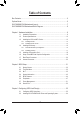
Table of Contents Box Contents....................................................................................................................6 Optional Items..................................................................................................................6 GA-F2A88XM-D3H Motherboard Layout..........................................................................7 GA-F2A88XM-D3H Motherboard Block Diagram.............................................................
Chapter 4 Drivers Installation.........................................................................................69 4-1 Installing Chipset Drivers................................................................................ 69 4-2 4-3 4-4 4-5 4-6 Application Software....................................................................................... 70 Technical Manuals........................................................................................... 70 Contact.......................
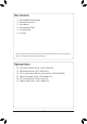
Box Contents 55 55 55 55 55 55 GA-F2A88XM-D3H motherboard Motherboard driver disk User's Manual Quick Installation Guide Four SATA cables I/O Shield The box contents above are for reference only and the actual items shall depend on the product package you obtain. The box contents are subject to change without notice. Optional Items 2-port USB 2.0 bracket (Part No. 12CR1-1UB030-6*R) eSATA bracket (Part No. 12CF1-3SATPW-4*R) 3.5" Front Panel with 2 USB 3.0/2.0 ports (Part No.
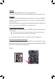
GA-F2A88XM-D3H Motherboard Layout KB_MS_USB ATX_12V DVI_VGA SYS_FAN2 Socket FM2+ HDMI OPTICAL LPT iTE® Super I/O USB_LAN F_USB30 R_USB30 SYS_FAN1 CPU_FAN ATX DDR3_1 BAT M_BIOS AMD A88X PCI SATA3 CODEC PCIEX4 F_AUDIO COM TPM F_USB2 F_USB1 F_PANEL -7- SATA3 0 1 2 3 SPDIF_O CLR_CMOS B_BIOS 4 6 5 7 DDR3_4 PCIEX1 Realtek® GbE LAN DDR3_3 GA-F2A88XM-D3H PCIEX16 DDR3_2 AUDIO
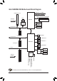
GA-F2A88XM-D3H Motherboard Block Diagram APU CLK+/- (100 MHz) 1 PCI Express x16 DISP CLK+/- (100 MHz) DDR3 2133/1866/1600/1333 MHz LAN PCIe CLK (100 MHz) RJ45 Dual Channel Memory AMD APU HDMI Realtek® GbE LAN PCI Express Bus x16 DVI-D x1 D-Sub x1 UMI 1 PCI Express x1 Dual BIOS PCI Express Bus 4 USB 3.0/2.0 x4 8 USB 2.0/1.1 AMD A88X 1 PCI Express x4 8 SATA 6Gb/s PCI Bus LPC Bus iTE® Super I/O 1 PCI For detailed product information/limitation(s), refer to "1-2 Product Specifications.
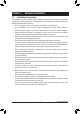
Chapter 1 1-1 Hardware Installation Installation Precautions The motherboard contains numerous delicate electronic circuits and components which can become damaged as a result of electrostatic discharge (ESD). Prior to installation, carefully read the user's manual and follow these procedures: •• Prior to installation, make sure the chassis is suitable for the motherboard. •• Prior to installation, do not remove or break motherboard S/N (Serial Number) sticker or warranty sticker provided by your dealer.
1-2 Product Specifications APU FM2+ Socket: - AMD A series processors - AMD Athlon™ series processors (Go to GIGABYTE's website for the latest CPU support list.) Chipset AMD A88X Memory 4 x 1.
Storage Interface USB Internal Connectors Chipset: 8 x SATA 6Gb/s connectors - Support for RAID 0, RAID 1, RAID 5, RAID 10, and JBOD Chipset: - 4 USB 3.0/2.0 ports (2 ports on the back panel, 2 ports available through the internal USB header) - 8 USB 2.0/1.
Unique Features Bundled Software Operating System Form Factor Support for @BIOS Support for Q-Flash Support for Xpress Install Support for EasyTune * Available functions in EasyTune may differ by motherboard model. Support for Smart Recovery 2 Support for ON/OFF Charge Norton® Internet Security (OEM version) Support for Windows 8.1/8/7 32-bit/64-bit Support for Windows XP-32bit Micro ATX Form Factor; 24.4cm x 24.4cm * If you plan to install Windows 8.
1-3 Installing the APU and APU Cooler Read the following guidelines before you begin to install the APU: •• Make sure that the motherboard supports the APU. (Go to GIGABYTE's website for the latest APU support list.) •• Always turn off the computer and unplug the power cord from the power outlet before installing the APU to prevent hardware damage. •• Locate the pin one of the APU. The APU cannot be inserted if oriented incorrectly.
B. Follow the steps below to correctly install the APU into the motherboard APU socket. •• Before installing the APU, make sure to turn off the computer and unplug the power cord from the power outlet to prevent damage to the APU. •• Do not force the APU into the APU socket. The APU cannot fit in if oriented incorrectly. Adjust the APU orientation if this occurs. Step 1: Completely lift up the APU socket locking lever.
1-3-2 Installing the CPU Cooler Follow the steps below to correctly install the APU cooler on the motherboard. Step 1: Apply an even and thin layer of thermal grease on the surface of the installed APU. Step 2: Hook the APU cooler clip to the mounting lug on one side of the retention frame. On the other side, push straight down on the APU cooler clip to hook it to the mounting lug on the retention frame.
1-4 Installing the Memory Read the following guidelines before you begin to install the memory: •• Make sure that the motherboard supports the memory. It is recommended that memory of the same capacity, brand, speed, and chips be used. (Go to GIGABYTE's website for the latest supported memory speeds and memory modules.) •• Always turn off the computer and unplug the power cord from the power outlet before installing the memory to prevent hardware damage. •• Memory modules have a foolproof design.
1-4-2 Installing a Memory Before installing a memory module, make sure to turn off the computer and unplug the power cord from the power outlet to prevent damage to the memory module. DDR3 and DDR2 DIMMs are not compatible to each other or DDR DIMMs. Be sure to install DDR3 DIMMs on this motherboard. Notch DDR3 DIMM A DDR3 memory module has a notch, so it can only fit in one direction. Follow the steps below to correctly install your memory modules in the memory sockets.
1-5 Installing an Expansion Card Read the following guidelines before you begin to install an expansion card: •• Make sure the motherboard supports the expansion card. Carefully read the manual that came with your expansion card. •• Always turn off the computer and unplug the power cord from the power outlet before installing an expansion card to prevent hardware damage.
1-6 Setup of the AMD Dual Graphics Configuration Combining the onboard GPU with a discrete graphics card, AMD's Dual Graphics technology can provide significantly advanced display performance for AMD platform. Read the following instructions on configuring a Dual Graphics system. A.
1-7 Back Panel Connectors USB 2.0/1.1 Port The USB port supports the USB 2.0/1.1 specification. Use this port for USB devices such as a USB keyboard/mouse, USB printer, USB flash drive and etc. PS/2 Keyboard/Mouse Port Use this port to connect a PS/2 mouse or keyboard. D-Sub Port The D-Sub port supports a 15-pin D-Sub connector and supports a maximum resolution of 1920x1200 (the actual resolutions supported depend on the monitor being used).
A. Triple Display Configurations: This motherboard provides three video output ports: D-Sub, DVI-D, and HDMI. Triple-display configurations are supported after you install motherboard drivers in OS. Only dual-display configurations are supported during the BIOS Setup or POST process. B. Playback of Blu-ray Disc™: In order to get better playback quality, when playing the Blu-ray Disc™, refer to the recommended system requirements (or better) below.
1-8 Internal Connectors 1 4 3 4 2 14 11 5 6 10 9 1) 2) 3) 4) 5) 6) 7) 8) ATX_12V ATX CPU_FAN SYS_FAN1/2 BAT SATA3 0/1/2/3/4/5/6/7 CLR_CMOS F_PANEL 13 15 12 8 9) 10) 11) 12) 13) 14) 15) 7 F_AUDIO SPDIF_O F_USB30 F_USB1/F_USB2 COM LPT TPM Read the following guidelines before connecting external devices: •• First make sure your devices are compliant with the connectors you wish to connect. •• Before installing the devices, be sure to turn off the devices and your computer.
1/2) ATX_12V/ATX (2x4 12V Power Connector and 2x12 Main Power Connector) With the use of the power connector, the power supply can supply enough stable power to all the components on the motherboard. Before connecting the power connector, first make sure the power supply is turned off and all devices are properly installed. The power connector possesses a foolproof design. Connect the power supply cable to the power connector in the correct orientation.
3/4) CPU_FAN/SYS_FAN1/SYS_FAN2 (Fan Headers) All fan headers on this motherboard are 4-pin. Most fan headers possess a foolproof insertion design. When connecting a fan cable, be sure to connect it in the correct orientation (the black connector wire is the ground wire). The speed control function requires the use of a fan with fan speed control design. For optimum heat dissipation, it is recommended that a system fan be installed inside the chassis. CPU_FAN: 1 CPU_FAN Pin No.
DEBUG PORT DEBUG PORT PORT DEBUG PORT PORT DEBUG PORT DEBUG PORT DEBUG PORT 6) SATA3 0/1/2/3/4/5/6/7 (SATA 6Gb/s Connectors) The SATA connectors conform to SATA 6Gb/s standard and are compatible with SATA 3Gb/s and SATA 1.5Gb/s standard. Each SATA connector supports a single SATA device. The AMD A88X Chipset supports RAID 0, RAID 1, RAID 5, RAID 10, and JBOD. Refer to Chapter 3, "Configuring SATA Hard Drive(s)," for instructions on configuring a RAID array.
8) F_PANEL (Front Panel Header) Connect the power switch, reset switch, speaker, chassis intrusion switch/sensor and system status indicator on the chassis to this header according to the pin assignments below. Note the positive and negative pins before connecting the cables.
9) F_AUDIO (Front Panel Audio Header) The front panel audio header supports Intel High Definition audio (HD) and AC'97 audio. You may connect your chassis front panel audio module to this header. Make sure the wire assignments of the module connector match the pin assignments of the motherboard header. Incorrect connection between the module connector and the motherboard header will make the device unable to work or even damage it. For HD Front Panel Audio: 9 1 10 2 Pin No.
F_AUDIO(H) 11) F_USB30 (USB 3.0/2.0 Header) The header conforms to USB 3.0/2.0 specification and can provide two USB ports. For purchasing the optional 3.5" front panel that provides two USB 3.0/2.0 ports, please contact the local dealer. 1 BIOS Switc DB_PORT G.QBOFM TPM w/housing Pin No. 1 2 3 4 5 6 7 8 9 10 Definition VBUS SSRX1SSRX1+ GND SSTX1SSTX1+ GND D1D1+ NC 10 1 11 1 Pin No.
13) COM (Serial Port Header) The COM header can provide one serial port via an optional COM port cable. For purchasing the optional COM port cable, please contact the local dealer. 9 10 1 2 Pin No. 1 2 3 4 5 6 7 8 9 10 Definition G.QBOFM NDCDNSIN NSOUT NDTRGND NDSRNRTSNCTSNRINo Pin DEBUG PORT 14) LPT (Parallel Port Header) The LPT header can provide one parallel port via an optional LPT port cable. For purchasing the optional LPT port cable, please contact the local dealer.
DB_PORT 15) TPM (Trusted Platform Module Header) You may connect a TPM (Trusted Platform Module) to this header. 19 1 20 2 TPM w/housing Voltage measurement module(X58A-OC) Pin No. Definition Pin No. Definition 1 2 3 4 5 6 7 8 9 10 LCLK GND LFRAME No Pin LRESET NC LAD3 LAD2 VCC3 LAD1 11 12 13 14 15 16 17 18 19 20 LAD0 GND NC ID SB3V SERIRQ GND NC NC SUSCLK Voltage measurement points(G1.
Chapter 2 BIOS Setup BIOS (Basic Input and Output System) records hardware parameters of the system in the CMOS on the motherboard. Its major functions include conducting the Power-On Self-Test (POST) during system startup, saving system parameters and loading operating system, etc. BIOS includes a BIOS Setup program that allows the user to modify basic system configuration settings or to activate certain system features.
2-1 Startup Screen The following startup Logo screen will appear when the computer boots. Function Keys Function Keys: : BIOS SETUP\Q-FLASH Press the key to enter BIOS Setup or to access the Q-Flash utility in BIOS Setup. : SYSTEM INFORMATION Press the key to display your system information. : BOOT MENU Boot Menu allows you to set the first boot device without entering BIOS Setup.
2-2 The Main Menu On the main menu of the BIOS Setup program, press arrow keys to move among the items and press to accept or enter a sub-menu. Or you can use your mouse to select the item you want.
BIOS Setup Menus M.I.T. Use this menu to configure the clock, frequency, and voltages of your CPU and memory, etc. Or check the system/CPU temperatures, voltages, and fan speeds. System Information Use this menu to configure the default language used by the BIOS and system time and date. This menu also displays information on the devices connected to the SATA ports.
2-3 M.I.T. Whether the system will work stably with the overclock/overvoltage settings you made is dependent on your overall system configurations. Incorrectly doing overclock/overvoltage may result in damage to CPU, chipset, or memory and reduce the useful life of these components. This page is for advanced users only and we recommend you not to alter the default settings to prevent system instability or other unexpected results.
`` M.I.T. Current Status This screen provides information on CPU/memory frequencies/parameters. `` Advanced Frequency Settings && BCLK/PCIe Clock Control Allows you to manually set the CPU base clock and PCIe bus frequency in 1 MHz increments. (Default: Auto) Important: It is highly recommended that the CPU frequency be set in accordance with the CPU specifications. && NB Clock (Mhz) Allows you to manually set the CPU North Bridge frequency. The adjustable range is from 800 MHz to 6000 MHz.
`` Advanced CPU Core Features && CPU Clock Ratio, CPU Frequency The settings above are synchronous to those under the same items on the Advanced Frequency Settings menu. && Core Performance Boost (Note) Allows you to determine whether to enable the Core Performance Boost (CPB) technology, a CPU performance-boost technology. (Default: Auto) && Turbo CPB (Note) Allows you to determine whether to improve CPU performance. (Default: Disabled) && CPB Ratio (Note) Allows you alter the ratio for the CPB.
&& CPU Core Control Allows you to determine whether to manually enable/disable CPU cores. Automatic mode allows the BIOS to enable all CPU cores (number of cores available depends on the CPU being used). (Default: Automatic mode) && APM Enables or disables Application Power Management. (Default: Enabled) && Extreme Memory Profile (X.M.P.) (Note) Allows the BIOS to read the SPD data on XMP memory module(s) to enhance memory performance when enabled. Disabled Disables this function.
`` Advanced Memory Settings && Extreme Memory Profile (X.M.P.) (Note), System Memory Multiplier, Memory Frequency(MHz) The settings above are synchronous to those under the same items on the Advanced Frequency Settings menu. && DRAM Timing Selectable Quick and Expert allows the memory timing settings below to be configurable. Options are: Auto (default), Quick, Expert. && Profile DDR Voltage When using a non-XMP memory module or Extreme Memory Profile (X.M.P.
`` Channel A/B Timing Settings This sub-menu provides memory timing settings for each channel of memory. The respective timing setting screens are configurable only when DRAM Timing Selectable is set to Quick or Expert. Note: Your system may become unstable or fail to boot after you make changes on the memory timings. If this occurs, please reset the board to default values by loading optimized defaults or clearing the CMOS values.
`` PC Health Status && Reset Case Open Status Disabled Keeps or clears the record of previous chassis intrusion status. (Default) Enabled Clears the record of previous chassis intrusion status and the Case Open field will show "No" at next boot. && Case Open Displays the detection status of the chassis intrusion detection device attached to the motherboard CI header. If the system chassis cover is removed, this field will show "Yes", otherwise it will show "No".
&& CPU Vcore/Dram Voltage/+3.3V/+5V/+12V Displays the current system voltages. && CPU/System Temperature Displays current CPU/system temperature. && CPU/System Fan Speed Displays current CPU/system fan speeds. && CPU Warning Temperature Sets the warning threshold for CPU temperature. When temperature exceeds the threshold, BIOS will emit warning sound. Options are: Disabled (default), 60oC/140oF, 70oC/158oF, 80oC/176oF, 90oC/194oF.
2-4 System Information This section provides information on your motherboard model and BIOS version. You can also select the default language used by the BIOS and manually set the system time. && System Language Selects the default language used by the BIOS. && System Date Sets the system date. The date format is week (read-only), month, date, and year. Use to switch between the Month, Date, and Year fields and use the or key to set the desired value.
2-5 BIOS Features && Boot Option Priorities Specifies the overall boot order from the available devices. For example, you can set hard drive as the first priority (Boot Option #1) and DVD ROM drive as the second priority (Boot Option #2). The list only displays the device with the highest priority for a specific type. For example, only hard drive defined as the first priority on the Hard Drive BBS Priorities submenu will be presented here.
&& OS Type Allows you to select the operating system to be installed. (Default: Other OS) && CSM Support Enables or disables UEFI CSM (Compatibility Support Module) to support a legacy PC boot process. Always Enables UEFI CSM. (Default) Never Disables UEFI CSM and supports UEFI BIOS boot process only. This item is configurable only when OS Type is set to Windows 8. && Boot Mode Selection Allows you to select which type of operating system to boot.
&& User Password Allows you to configure a user password. Press on this item, type the password, and then press . You will be requested to confirm the password. Type the password again and press . You must enter the administrator password (or user password) at system startup and when entering BIOS Setup. However, the user password only allows you to make changes to certain BIOS settings but not all.
2-6 Peripherals && IOMMU Enables or disables AMD IOMMU support. (Default: Disabled) && OnChip SATA Channel Enables or disables the integrated SATA controllers. (Default: Enabled) && OnChip SATA Type Enables or disables RAID for the SATA controllers integrated in the Chipset or configures the SATA controllers to AHCI mode. Native IDE Configures the SATA controller to IDE mode. RAID Enables RAID for the SATA controller. AHCI Configures the SATA controllers to AHCI mode.
&& Legacy USB Support Allows USB keyboard/mouse to be used in MS-DOS. (Default: Enabled) && XHCI Hand-off Determines whether to enable XHCI Hand-off feature for an operating system without XHCI Hand-off support. (Default: Enabled) && EHCI Hand-off Determines whether to enable EHCI Hand-off feature for an operating system without EHCI Hand-off support. (Default: Disabled) && Port 60/64 Emulation Enables or disables emulation of I/O ports 64h and 60h.
SB PCIe Slot Video Sets the PCI Express graphics card on the PCI Express slot controlled by the South Bridge as the first display. && Integrated Graphics Enables or disables the onboard graphics function. Auto The BIOS will automatically enable or disable the onboard graphics depending on the graphics card being installed. (Default) Disabled Disables the onboard graphics. Force Always activates the onboard graphics, whether or not a PCI Express card is installed.
`` Super IO Configuration This section provides information on the super I/O chip and allows you to configure the serial port and parallel port. && Serial Port A Enables or disables the onboard serial port. (Default: Enabled) && Parallel Port Enables or disables the onboard parallel port (LPT). (Default: Enabled) && Device Mode This item is configurable only when Parallel Port is set to Enabled. It allows you to select an operating mode for the onboard parallel (LPT) port.
2-7 Power Management && Resume by Alarm Determines whether to power on the system at a desired time. (Default: Disabled) If enabled, set the date and time as following: Wake up day: Turn on the system at a specific time on each day or on a specific day in a month. Wake up hour/minute/second: Set the time at which the system will be powered on automatically.
&& Power On By Keyboard Allows the system to be turned on by a PS/2 keyboard wake-up event. Note: To use this function, you need an ATX power supply providing at least 1A on the +5VSB lead. Disabled Disables this function. (Default) Password Set a password with 1~5 characters to turn on the system. Keyboard 98 Press POWER button on the Windows 98 keyboard to turn on the system. Any key Press any key to turn on the system.
2-8 Save & Exit && Save & Exit Setup Press on this item and select Yes. This saves the changes to the CMOS and exits the BIOS Setup program. Select No or press to return to the BIOS Setup Main Menu. && Exit Without Saving Press on this item and select Yes. This exits the BIOS Setup without saving the changes made in BIOS Setup to the CMOS. Select No or press to return to the BIOS Setup Main Menu.
BIOS Setup - 54 -
Chapter 3 Configuring SATA Hard Drive(s) RAID Levels RAID 0 Minimum ≥2 Number of Hard Drives Array Capacity Number of hard drives * Size of the smallest drive Fault Tolerance No RAID 1 2 Size of the smallest drive Yes RAID 5 ≥3 (Number of hard drives -1) * Size of the smallest drive Yes RAID 10 ≥4 (Number of hard drives/2) * Size of the smallest drive Yes To configure SATA hard drive(s), follow the steps below: A. B. C. D. Install SATA hard drive(s) in your computer.
B. Configuring SATA controller mode in BIOS Setup Make sure to configure the SATA controller mode correctly in system BIOS Setup. Step 1: Turn on your computer and press to enter BIOS Setup during the POST (Power-On Self-Test). Make sure OnChip SATA Channel is enabled. To enable RAID for the SATA3 0/1/2/3 connectors, set OnChip SATA Type to RAID. To enable RAID for the SATA3 4~SATA3 6 and eSATA connectors, set OnChip SATA Type to RAID and set OnChip SATA Port4-7 Type to As SATA Type (Figure 1).
C-1. UEFI RAID Configuration This mode supports Windows 8 64-bit installation only. To configure UEFI RAID, you need to prepare a USB flash drive using FAT 32 file format and copy all files (including the UEFI RAID utility rcadm.efi) in the \BootDrv\UEFI RAID Utility folder in your motherboard driver disk to the flash drive. Then follow the steps below. Step 1: In BIOS Setup, go to BIOS Features and set OS Type to Windows 8 and CSM Support to Never. (Figure 2) Save the changes and exit BIOS Setup.
Checking Disk Information To see the hard drive information, enter the following commands and press . You will see CONTROLLER LIST and DISK LIST displayed on the screen. rcadm -M -qa (Figure 4) fs0:\> rcadm -M -qa Figure 4 Creating a RAID Array To create a RAID array, refer to the following examples to enter the commands and press . When succeeded, the message which says "created sucessfully" will appear. Example 1: Create a RAID 0 array with Drive 0 and Drive 1 and the array size is 40 GB.
Deleting an Array To delete an array, enter the following commands and press . rcadm -D -a 1 (Figure 7) ("D"=Delete a array, "a 1"=Array 1, to delete all arrays, enter "a *") When prompted to confirm, enter YES to delete or NO to cancel, and then press . fs0:\>rcadm -D -a 1 Delete Array 1, are you sure?(YES, NO): yes deleting array 1 deleting array //./Core1/Route0/Device 1 fs0:\> Figure 7 To exit the UEFI RAID utility, enter "exit" and press .
C-2. Configuring Legacy RAID ROM Enter the legacy RAID BIOS setup utility to configure a RAID array. Skip this step and proceed with the installation of Windows operating system for a non-RAID configuration. Steps: After the POST memory test begins and before the operating system boot begins, look for a message which looks like that in Figure 8 below. Press + to enter the RAID BIOS setup utility. AMD-RAID Controller BIOS (6.1.1-00075) (c) 2012-2013 Advanced Micro Devices, Inc.
The selection bar will move to the Disks section on the right of the screen. Select the hard drives to be included in the RAID array. Use the up or down arrow key to select a hard drive and press . The selected hard drive will be shown in green. To use all of the hard drives, simply press to select all. Then press and the selection bar will move to the User Input section on the left bottom of the screen. (Figure 10) AMD-RAID Array Configuration (Build: 6.1.
Select a caching mode. Options include Read/Write, Read Only, and None. Then press to proceed. AMD-RAID Array Configuration (Build: 6.1.1-00075) Read and Write-back Caching.
Deleting an Array The Delete Array(s) menu option allows for deletion of disk array assignments. Deleting an existing disk array could result in loss of data. Record all array information including the array type, the disk members, and stripe block size in case you wish to undo a deletion. 1. Select Delete Array(s) in the Main Menu and press . 2. In the Arrays section, press the key on the array you want to delete and then press to proceed. 3.
3-2 Installing the SATA RAID/AHCI Driver and Operating System With the correct BIOS settings, you are ready to install the operating system. A. Installing Windows 8/7 (The following instructions use Windows 8 as the example operating system.) Step 1: You need to install the SATA RAID/AHCI driver during the OS installation. Use an alternative system to copy the SATA RAID/AHCI driver from the motherboard driver disk to a USB flash drive. Copy the Hw8_A88 folder under BootDrv in the driver disk.
B. Installing Windows XP (32-bit) Before installing Windows XP, connect a USB floppy disk drive to your computer first because you need to install the SATA RAID/AHCI driver from a floppy disk that contains the driver during the OS installation. Without the driver, the hard drive(s) may not be recognized during the Windows setup process. First, copy the driver from the motherboard driver disk to a floppy disk. Refer to the methods below.
Refer to the following for installing the driver during the Windows setup process. Step 1: Restart your system to boot from the Windows XP setup disk and press as soon as you see the message "Press F6 if you need to install a 3rd party SCSI or RAID driver." A screen will then appear asking you to specify an additional SCSI adapter. Press . Step 2: Insert the floppy disk containing the SATA RAID/AHCI driver and press . Then a controller menu similar to that in Figure 3 will appear.
Rebuilding an Array: Rebuilding is the process of restoring data to a hard drive from other drives in the array. Rebuilding applies only to fault-tolerant arrays such as RAID 1, RAID 5, and RAID 10 arrays. To replace the old drive, make sure to use a new drive of equal or greater capacity. The procedures below assume a new drive is added to replace a failed drive to rebuild a RAID 1 array.
Configuring SATA Hard Drive(s) - 68 -
Chapter 4 4-1 Drivers Installation •• Before installing the drivers, first install the operating system. (The following instructions use Windows 8 as the example operating system.) •• After installing the operating system, insert the motherboard driver disk into your optical drive. Click on the message "Tap to choose what happens with this disc" on the top-right corner of the screen and select "Run Run.exe." (Or go to My Computer, double-click the optical drive and execute the Run.exe program.
4-2 Application Software This page displays all the utilities and applications that GIGABYTE develops and some free software. You can click the Install button on the right of an item to install it. 4-3 Technical Manuals This page provides the content descriptions for this driver disk.
4-4 Contact For the detailed contact information of the GIGABYTE Taiwan headquarter or worldwide branch offices, click the URL on this page to link to the GIGABYTE website. 4-5 System This page provides the basic system information.
4-6 Download Center To update the BIOS, drivers, or applications, click the Download Center button to link to the GIGABYTE website. The latest version of the BIOS, drivers, or applications will be displayed.
Chapter 5 5-1 Unique Features BIOS Update Utilities GIGABYTE motherboards provide two unique BIOS update tools, Q-Flash™ and @BIOS™. GIGABYTE Q-Flash and @BIOS are easy-to-use and allow you to update the BIOS without the need to enter MS-DOS mode. Additionally, this motherboard features the DualBIOS™ design, which enhances protection for the safety and stability of your computer by adding one more physical BIOS chip.
B. Updating the BIOS In the main menu of Q-Flash, use the keyboard or mouse to select an item to execute. When updating the BIOS, choose the location where the BIOS file is saved. The following procedure assumes that you save the BIOS file to a USB flash drive. Step 1: 1. Insert the USB flash drive containing the BIOS file into the computer. In the main menu of Q-Flash, select Update BIOS From Drive. •• The Save Main BIOS to Drive option allows you to save the current BIOS file.
Step 4: During the POST, press to enter BIOS Setup. Select Load Optimized Defaults on the Save & Exit screen and press to load BIOS defaults. System will re-detect all peripheral devices after a BIOS update, so we recommend that you reload BIOS defaults. Select Yes to load BIOS defaults Step 5: Select Save & Exit Setup and press . And then select Yes to save settings to CMOS and exit BIOS Setup. The procedure is complete after the system restarts.
5-1-2 Updating the BIOS with the @BIOS Utility A. Before You Begin 1. 2. 3. 4. In Windows, close all applications and TSR (Terminate and Stay Resident) programs. This helps prevent unexpected failures when performing a BIOS update. During the BIOS update process, ensure the Internet connection is stable and do NOT interrupt the Internet connection (for example, avoid a power loss or switching off the Internet). Failure to do so may result in a corrupted BIOS or a system that is unable to start.
5-2 EasyTune 6 GIGABYTE's EasyTune 6 is a simple and easy-to-use interface that allows users to fine-tune their system settings or do overclock/overvoltage in Windows environment. The user-friendly EasyTune 6 interface also includes tabbed pages for CPU and memory information, letting users read their system-related information without the need to install additional software.
5-3 Smart Recovery 2 Smart Recovery 2 allows you to back up a partition as an image file every hour. You can use these images to restore your system or files when needed. The Smart Recovery 2 main menu: Button Description Allows you to select the source and destination Settings partition Backup Now Allows you to perform the backup immediately File Allows you to recover your files from the backup image Recovery... System Allows you to recover your system from the backup image Recovery...
Recovering your system with Smart Recovery 2 (Windows 8/7 only): Steps: 1. Click the File Recovery button on the main menu. 2. Select the location where your backup is saved. 3. Use the time slider to select a time point. 4. Select a partition backup created on the selected time point and click Restore. 5. Confirm whether to restart your system to proceed with the restore immediately or later. Once you respond "Yes" the system will restart to the Windows recovery environment.
Unique Features - 80 -
Chapter 6 6-1 Appendix Configuring Audio Input and Output 6-1-1 Configuring 2/4/5.1/7.1-Channel Audio The motherboard provides three audio jacks on the back panel which support 2/4/5.1/7.1 (Note)-channel audio. The picture to the right shows the default audio jack assignments. The integrated HD (High Definition) audio provides jack retasking capability that allows the user to change the function for each jack through the audio driver.
The pictures to the right show the 7.1-channel speaker configurations. 7.1-Channel Speakers: Front Speaker Out Rear Speaker Out Center/Subwoofer Speaker Out Side Speaker Out Step 2: Connect an audio device to an audio jack. The The current connected device is dialog box appears. Select the device according to the type of device you connect. Then click OK. Step 3: On the Speakers screen, click the Speaker Configuration tab. In the Speaker Configuration list, select Stereo, Quadraphonic, 5.
C. Activating an AC'97 Front Panel Audio Module If your chassis provides an AC'97 front panel audio module, to activate the AC'97 functionality, click the tool icon on the Speaker Configuration tab. On the Connector Settings dialog box, select the Disable front panel jack detection check box. Click OK to complete. D. Muting the Back Panel Audio (For HD Audio Only) Click Device advanced settings on the top right corner on the Speaker Configuration tab to open the Device advanced settings dialog box.
6-1-2 Configuring S/PDIF Out The S/PDIF Out jack can transmit audio signals to an external decoder for decoding to get the best audio quality. 1. Connecting a S/PDIF Out Cable: Connect a S/PDIF optical cable to the corresponding S/PDIF out connector as shown below and an external decoder for transmitting the S/PDIF digital audio signals. Connects to a S/PDIF optical cable 2.
6-1-3 Configuring Microphone Recording Step 1: After installing the audio driver, the HD Audio Manager icon will appear in the notification area. Double-click the icon to access the HD Audio Manager. Step 2: Connect your microphone to the Mic in jack (pink) on the back panel or the Mic in jack (pink) on the front panel. Then configure the jack for microphone functionality. Note: The microphone functions on the front panel and back panel cannot be used at the same time. Step 3: Go to the Microphone screen.
Step 5: To open the Sounder Recorder, move the mouse cursor to the bottom left corner of the screen, click the Start icon to switch to the Start screen (or press the Windows button on the keyboard). Right-click on the screen and click the All apps icon on the bottom right corner of the screen to access the Apps screen. Step 6: On this screen, click Sound Recorder for audio recording.
Step 2: On the Recording tab, right-click on an empty space and select Show Disabled Devices. Step 3: When the Stereo Mix item appears, right-click on this item and select Enable. Then set it as the default device. Step 4: Now you can access the HD Audio Manager to configure Stereo Mix and use Sound Recorder to record the sound. 6-1-4 Using the Sound Recorder A. Recording Sound 1. Make sure you have connected the sound input device (e.g. microphone) to the computer. 2.
6-2 Troubleshooting 6-2-1 Frequently Asked Questions To read more FAQs for your motherboard, please go to the Support & Downloads\FAQ page on GIGABYTE's website. Q: Why is the light of my keyboard/optical mouse still on after the computer shuts down? A: Some motherboards provide a small amount of standby power after the computer shuts down and that's why the light is still on.
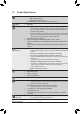
6-2-2 Troubleshooting Procedure If you encounter any troubles during system startup, follow the troubleshooting procedure below to solve the problem. START Turn off the power. Remove all peripherals, connecting cables, and power cord etc. Make sure the motherboard does not short-circuit with the chassis or other metal objects. No Yes Isolate the short circuit. The problem is verified and solved. Check if the CPU cooler is attached to the CPU securely.
A When the computer is turned on, is the CPU cooler running? Yes No The power supply, CPU or CPU socket might fail. The problem is verified and solved. Check if there is display on your monitor. Yes No The graphics card, expansion slot, or monitor might fail. The problem is verified and solved. Turn off the computer. Plug in the keyboard and mouse and restart the computer. Check if the keyboard is working properly. Yes No The keyboard or keyboard connector might fail.
Regulatory Statements Regulatory Notices This document must not be copied without our written permission, and the contents there of must not be imparted to a third party nor be used for any unauthorized purpose. Contravention will be prosecuted. We believe that the information contained herein was accurate in all respects at the time of printing. GIGABYTE cannot, however, assume any responsibility for errors or omissions in this text.
Appendix - 92 -
- 93 - Appendix
Appendix - 94 -
Contact Us •• GIGA-BYTE TECHNOLOGY CO., LTD. Address: No.6, Bao Chiang Road, Hsin-Tien Dist., New Taipei City 231,Taiwan TEL: +886-2-8912-4000 FAX: +886-2-8912-4005 Tech. and Non-Tech. Support (Sales/Marketing) : http://ggts.gigabyte.com.tw WEB address (English): http://www.gigabyte.com WEB address (Chinese): http://www.gigabyte.tw •• G.B.T. INC. - U.S.A. TEL: +1-626-854-9338 FAX: +1-626-854-9326 Tech. Support: http://ggts.gigabyte.com.tw Warranty Info: http://rma.gigabyte.us Web address: http://www.
•• G.B.T. TECHNOLOGY TRADING GMBH - Germany WEB address : http://www.gigabyte.de •• G.B.T. TECH. CO., LTD. - U.K. WEB address : http://www.giga-byte.co.uk •• Giga-Byte Technology B.V. - The Netherlands WEB address : http://www.giga-byte.nl •• GIGABYTE TECHNOLOGY FRANCE - France WEB address : http://www.gigabyte.fr •• Sweden WEB address : http://www.gigabyte.se •• Italy WEB address : http://www.giga-byte.it •• Spain WEB address : http://www.giga-byte.es •• Greece WEB address : http://www.gigabyte.com.