
Owner's manual

IC Live Users Manual - Models ICL-R & IC215S-R
33
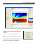
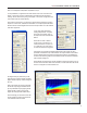
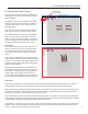
You should know the physical dimensions of the area(s) you want to cover, so the
next logical step is to set up the audience area(s) using the Audience Area section on
the right side of the Beam Steering screen.
To simplify this step, Beam Steering provides ve templates, the Standard one used
as the default starting point and four others; Small Arena, Large Arena, Open Air and
Theater. These templates are available by clicking on the Area Presets button. You
should become familiar with these templates, so we suggest you try each one of them
and then choose the one that comes closest to matching your project. Note how the
number of areas and the size of the Audience Areas change from one template to
another.
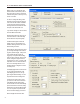
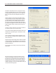
Once you have selected the template, alter the Audience Area size(s) and location(s)
to match your project’s dimensions. Notice that you can also add or delete up to a
maximum of 3 Audience Areas by using the Number eld and associated drop down
arrow.
The Start eld establishes the beginning point of the Audience Area relative to the “0”
point of the graph. The Start point is usually the rst row of seating. Height 1 is the
height of the front of the Audience Area. It usually is “0” for the front of the rst oor
area.
Length is the physical length of the Audience Area from the front edge to the rear
edge. Height 2 is the elevation (height) of the rear of the Audience Area above the “0”
plane.
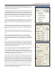
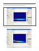
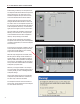
The next step is to congure the steerable column(s) you will be using in your
project,i.e., to position them, dene the beam(s), etc. using the IC Conguration
section on the left side of the window. See graphic to the lower right. The down arrow
associated with the Setup eld allows you to select between arrays in multiple array
systems.
Now, it’s time to locate (position) the steerable column. Usually it will be on the front
wall (X = 0.00) in the beam steering Project display. If it will be placed at the front of
the stage away from the front wall, for example, move it forward by inserting its cor-
rect location. Note that after you insert a gure in the eld, you need to press Enter on
your keyboard to OK the change in location.
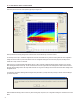
The Y eld controls the height of the column array by positioning the bottom of the
column above the Floor level (the “0” level) The default position is 6.56 feet (2
meters). The Mechanical Angle eld tilts the column forward or backward (minus [-]
numbers tip it back and plus [+] numbers tilt it forward). This parameter is usually left
at 0.0 since the normal position for IC Live arrays is at against a wall and the array’s
output digitally steered down onto the audience area.
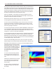
The next step is to choose the number of Beams using the Beams eld and its associ-
ated drop down menu. One of the unique features of Iconyx steerable arrays is the
ability to generate either single or multiple lobes. We’ll be discussing multiple lobes
later in this tutorial, so for now accept the default 1 beam (single lobe) conguration.
Beam Size lets you choose the Array’s opening angle which controls the sharpness of
the vertical lobe (beam). Try it out using the drop down arrow. Notice how the open-
ing angle of the array in the graphic varies as you choose different opening angles.
The High-Pass at [Hz] control allows you to insert a high pass lter into individual
beams. This new Beamware feature is used to balance the system’s low, mid and
high frequency content to improve intelligibility,