
Owner's manual


IC Live Users Manual - Models ICL-R & IC215S-R
7
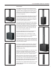
5. Slide the two joining bars
into the channels as shown.
6. Lock the joining bars into place
with the short quick release pins to
complete the physical assembly.
Assembly (continued)
Note: If you are assembling a “triple stack”, follow the same procedure to place the third module on top of the second module with one excep-
tion. The woofer sections of the second and third modules should be joined together. If in doubt, refer to page 65 for proper module orientation.
The procedure for mounting an ICL-R array onto an IC215S-R subwoofer is the same. The only difference is the array’s rear cylinder sleeve
drops into the socket on either the top or the end of the subwoofer. When mounting a stack (two ICL-R arrays) on top of one or two subwoof-
ers, it is best to rst mount the lower line array module onto the subwoofer and then attach the top line array. It’s easier and safer. Do not
attempt to mount a stacked ICL-R array onto a subwoofer standing vertically. The resulting assembly is unstable.
Note: If you should be using an IC212S-R dual 12” subwoofer, you will need a pair of MET001 joining bars to replace the ones
suppliedwith the ICL-R array module. The ones supplied with the ICL-R will not work with the IC212S-R
Master / Slave Settings
The next step in Master & Slave systems is to electrically link the modules
together and verify the Master/Slave assignment is correct The bottom
module always functions as the Master and the upper modules as Slaves.
The module directly above the Master module is identied as Slave 1 and
the module above it as Slave 2. .All incoming signal and AC power connec-
tions should be made to the Master..
Plug one end of the short CAT5 linking cable into the lower interconnect
socket on the Master (lower) module and the other end into the upper socket
on the upper module. Then plug one end of the short AC power cable into
the looping power socket on the lower module and the other end into the
power socket on the upper module. Follow the same procedure to connect a
third module, if one is provided.
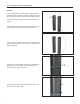
The next step is to set the two dip switches that identify each module. Set
the Master switches rst; The graphic directly below the two dip switches
shows the proper setting for a Master module (both switches in the down
position). Then set the Slave module(s) dip switches following the settings
shown in the graphic. Note that the Slave #3 switch is for future use.
On All Master systems, set each module’s dip switches to the Master posi-
tion.
Note: If you connected power to the array before setting the dip switches,
you will need to turn it off or disconnect it at the source and then reconnect it
before the dip switch settings will take effect. When properly set in Master &
Skave systems the digital readouts will both read 20 in a dual array and 30
in a three module array.
Master
setting
Slave #1
setting
Slave #2
setting
Slave #3
setting