WANDERER SERIES 30A PWM Version 1.
Important Safety Instructions Please save these instructions. This manual contains important safety, installation, and operating instructions for the charge controller. The following symbols are used throughout the manual: WARNING CAUTION NOTE Indicates a potentially dangerous condition.
Battery Safety Do NOT let the positive (+) and negative (-) terminals of the battery touch each other. Use only sealed lead-acid, flooded, gel or lithium batteries which must be deep cycle. Explosive battery gases may be present while charging. Be certain there is enough ventilation to release the gases. Be careful when working with large lead acid batteries. Wear eye protection and have fresh water available in case there is contact with the battery acid.
Table of Contents General Information 04 Optional Components 06 Identification of Parts 07 Installation 07 Mounting Recommendations Operation 10 LED Indicators 10 System Status Troubleshooting 11 Maintenance 12 Fusing 12 Technical Specifications 13 Electrical Specifications 13 Battery Charging Parameters 13 Dimensions 03 07 14
General Information The Wanderer is an advanced charge controller for off-grid solar applications and can be used with a 12V battery or battery bank. Integrating highly efficient PWM charging, the Wanderer increases battery life and improves system performance. The controller comes equipped with fully comprehensive self-diagnostics and electronic protection functions to prevent damage from installation mistakes or system faults. Key Features Optimized for 12 VDC system voltage 30A charging capacity.
VOLTAGE NIGHT BULK CHARGE BOOST FLOAT NIGHT TIME Bulk Charge: This algorithm is used for day to day charging. It uses 100% of available solar power to recharge the battery and is equivalent to constant current. Boost Charge: When the battery has charged to the Boost voltage set-point, it undergoes an absorption stage which is equivalent to constant voltage regulation to prevent heating and excessive gassing in the battery. The Boost time is 120 minutes.
Lithium Battery Activation The Wanderer PWM charge controller has a reactivation feature to awaken a sleeping lithium battery. The protection circuit of lithium battery will typically turn the battery off and make it unusable if over-discharged. This can happen when storing a lithium battery pack in a discharged state for any length of time as self-discharge would gradually deplete the remaining charge.
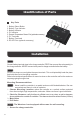
Identification of Parts ④ Key Parts 1. Battery Select Button 2. Battery Type Indicator 3. Battery Indicator 4. PV Indicator 5. Remote Temperature Sensor Port (optional accessory) 6. PV Terminals 7. Battery Terminals 8. RS-232 Port (optional accessory) ⑤ ⑥ ⑦ ③ ② ① ⑧ Installation WARNING Connect battery terminal wires to the charge controller FIRST then connect the solar panel(s) to the charge controller. NEVER connect solar panel to charge controller before the battery.
Battery Solar Panel 08
Bluetooth Module Communication (optional) Temperature Sensor (optional, not polarity sensitive) Place the sensor close to the battery 09
Operation After connecting the battery to the charge controller, the controller will turn on automatically. Operation of this controller is very simply. Users set the battery type, and leave the rest of the work to the charge controller. Setting Battery Type Simply hold the gray button for approximately 7 seconds until the LED flashes.
System Status Troubleshooting Description Battery is low-voltage Troubleshoot Use a multi-meter to verify the rated battery voltage. Disconnect any loads connected to the battery to allow it to charge. Battery is over-voltage Use a multi-meter to check the voltage of the battery. Make sure the battery voltage is not exceeding the rated specification of the charge controller. Disconnect battery. PV is over-voltage Use a multi-meter to check the voltage of the panels.
Maintenance For best controller performance, it is recommended that these tasks be performed from time to time. 1. Check that controller is mounted in a clean, dry, and ventilated area. 2. Check wiring going into the charge controller and make sure there is no wire damage or wear. 3. Tighten all terminals and inspect any loose, broken, or burnt up connections. Fusing NEC Maximum Current for different Copper Wire Sizes AWG Max.
Technical Specifications Electrical Specifications Description Parameter Nominal system voltage Rated Charge Current Max. PV Input Voltage Self-Consumption Temp. Compensation Max. Terminal Size Working Temperature Net Weight Dimensions Enclosure Communication Certification 12 VDC 30A 25 VDC ≤10mA -3mV/°C/2V 10mm 8 AWG -35°C to +45°C / -20°F to 113°F 0.29 kg 0.65 lb. 163.8 x 109.6 x 44.7mm 6.5 x 4.3 x 1.
Battery Charging Parameters Battery Type SEALED/AGM GEL FLOODED 16 V 16 V 16 V 16 V Over-voltage Recover 15.5 V 15 V 15.5 V 15 V 15.5 V 15 V Boost Charge Voltage 14.6 V 14.2 V 14.6 V 15.5 V 15 V 14.2 V (User:12.6-16V) Float Charge Voltage 13.8 V 13.8 V 13.8 V ----- Equalization Voltage ----- ----- 14.8 V ----- Boost Return Voltage 13.2 V 13.2 V 13.2 V 13.2 V Under Voltage Warning Under Voltage Recover Over-discharge Warning 12V 12V 12V 12.1V 12.2V 12.2V 12.2V 12.
RENOGY.COM Renogy reserves the right to change the contents of this manual without notice. US 2775 E Philadelphia St, Ontario, CA 91761, USA 909-287-7111 www.renogy.com support@renogy.com CN 苏州高新区科技城培源路1号5号楼-4 JP https://www.renogy.jp supportjp@renogy.com CA https://ca.renogy.com supportca@renogy.com AU https://au.renogy.com supportau@renogy.com UK https://uk.renogy.com supportuk@renogy.com DE https://de.renogy.com supportde@renogy.com 400-6636-695 https://www.renogy.cn support@renogy.