
Full Product Manual


16
most batteries this could cause damage. Please refer to the batteries owner’s manual or
contact the manufacturer to see if this stage is needed.
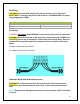
Transfer Switch
The inverters come with a 20A/30A transfer switch that allows the inverters to switch
between AC shore power and AC inverter mode (DC to AC) in a matter of 10
milliseconds. The inverter will automatically switch to battery power when the AC input
voltage drops below 90VAC.
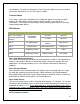
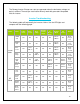
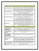
DIP Switches
Switch Number
Switch Function
Position: 1
Position: 0
SW 1 (AC Priority)
Low Battery
Disconnect
10.5VDC
10.0VDC
SW 1 (Battery
Priority)
11.5VDC
10.5VDC
SW 2
AC Input Range
90-130 VAC
(40Hz+)
100-130 VAC
SW 3
Power Saver
Detect load every 3s
Inverter Off
SW 4
Frequency Switch
60Hz
50Hz
SW 5
Battery/AC Priority
Battery Priority
AC Priority
SW 1 (Low Battery Disconnect):
This switch can change the low battery disconnect between 10.0V-11.5V. Depending on
whether shore power is present or not the low voltage set point will change. For most
applications, the voltage should be set to 11.5V to prevent the batteries from being
depleted.
SW 2 (AC Input Range):
Most electronics have a recommended AC voltage range and staying within this range
will allow the electronic to function normally. Some electronics will function between
100-130VAC 60Hz while other accept a lower frequency 40-60HZ. If the AC source falls
below 50Hz or 100VAC then position 1 will need to be used.
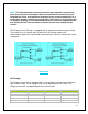
SW 3 (Power Saver):
The inverter’s power saver mode is activated when position 1 is selected. The inverter
will detect a load for 250ms every 3 seconds and if a load is detected the inverter will start
outputting AC power. NOTE: If the switch position is set to 0 and power saver mode is
selected on the inverter main power switch, then no AC power will be outputted unless
there is shore power connected to the inverter.
SW 4 (Frequency Switch):