Eclipse Solar Suitcase Renogy 100W | 200W 2775 E. Philadelphia St.
Important Safety Instructions Please save these instructions. This manual contains important safety, installation, and operating instructions for the charge controller. The following symbols are used throughout the manual to indicate potentially dangerous conditions or important safety information. WARNING: Indicates a potentially dangerous condition. Use extreme caution when performing this task.
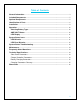
Table of Contents General Information ......................................................................................................................................... 3 Included Components .................................................................................................................................... 5 Optional Components ....................................................................................................................................
General Information The Renogy Solar Suitcase combine highly efficient monocrystalline solar panels with a 20A Voyager charge controller to create an easy-to-use, ‘plug and play’ system. This system is specifically designed for mobile off-grid applications, where space and weight limitations are abundant. The Solar Suitcase models support 12V deep cycle battery varieties such as sealed-lead acid, gel, and flooded.
Four Charging Stages The Voyager charge controller has a 4-stage battery charging algorithm for a rapid, efficient, and safe battery charging. They include: Bulk Charge, Boost Charge, Float Charge, and Equalization. Bulk Charge: This algorithm is used for day to day charging. It uses 100% of available solar power to recharge the battery and is equivalent to constant current.
Included Components MC4 to Alligator Clips w/ Fuse Used for connecting charge controller to battery. The entire cable from the charge controller to the alligator clips measures 9.9 feet with an inline fuse of 10A Optional Components Optional components that require a separate purchase: Remote Temperature Sensor Measures the temperature at the battery and uses this data for very accurate temperature compensation. The sensor is supplied with a 9.9 feet cable length that connects to the charge controller.
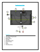
Identification of Parts 1 2 3 8 4 7 6 5 Key Parts 1. 2. 3. 4. 5. 6. 7. 8. 9.
2 1 3 4 6 5 7 Key Parts 1. 2. 3. 4. 5. 6. 7.
Installation 1. Unlatch and unfold unit then connect MC4 Connectors 2.
3.
Operation When the controller powers on, the Voyager will run a self-quality check mode and automatically display the figures on LCD before going into auto work. Self-test starts, digital meter segments test Software version test Rated voltage Test Rated Current Test External battery temperature sensor test (if connected) Selecting Battery Type WARNING: Incorrect battery type setting may damage your battery. Please check your battery manufacturer’s specifications to when selecting battery type.
Normal Sequencing Display ºC V A AH NOTE: The following is an alternative display voltage for when the battery is Fully charged V LED Display System Status Icons LED Behavior LED Indicators LED Color Soft-chargeing Bulk charging ( BV < 11.5V ) Bulk charging ( 11.5V < BV < 12.5V ) Bulk charging ( BV > 12.
LED Error Behavior LED Indicators LED Color Solar good, BV < 3V Solar good battery reversed Solar good, battery over-voltage Solar off, battery over-voltage Solar good, battery over 65⁰C Battery good, solar reversed Battery good, solar overvoltage Over Temperature Protection Error Code Screen RED BLUE RED ORANGE GREEN GREEN ON OFF FLASH OFF OFF OFF ‘b01’ FLASH ON OFF FLASH OFF OFF OFF ‘b02’ FLASH ON OFF FLASH FLASH FLASH OFF ‘b03’ FLASH OFF OFF FLASH FLASH FLASH OFF ‘
Maintenance For best controller performance, it is recommended that these tasks be performed from time to time. 1. Check wiring going into the charge controller and make sure there is no wire damage or wear. 2. Tighten all terminals and inspect any loose, broken, or burnt up connections 3. Make sure readings in the LCD and LED are consistent. Frequently Asked Questions Q. Can the kit charge two or more 12V batteries connected in parallel? A.
Technical Specifications Solar Panel Parameters Description Maximum Power Open Circuit Voltage (Voc) Short Circuit Current (Isc) Maximum Power Voltage (Vmp) Maximum Power Current (Imp) Cell Type Operating Temperature Folded Size Net Weight 100 W Parameters 100 W 21.6 V 6.10 A 17.6 V 5.68 A Monocrystalline −40°F to +185°F 21.1 X 21.5 X 3.1 in 19.40 lbs. 200 W Parameters 200 W 21.2 V 12.12 A 17.7 V 11.3 A Monocrystalline −40°F to +185°F 41.3 X 21.1 X 3.1 in 33.60 lbs.
Operating Temperature Meter Operating Temperature Storage Temperature Range Temp. Comp. Coefficient Temp. Comp. Range Operating Humidity -40 ⁰F to +140 ⁰F -4 ⁰F to +140 ⁰F -40 ⁰F to +185 ⁰F -24mV / °C -4°F ~ 122°F 100% ( No condensation ) Battery Charging Parameters Charging Stages Soft-Charge Output battery voltage is 3V-10VDC, Current = half of the solar panel current Bulk 10VDC to 14VDC Current = Rated Charge Current Absorption Constant voltage until current drops to 0.75/1.0 amps and holds for 30s.
Float Voltage—once the charge controller recognizes the set float voltage, it will commence floating. The battery is supposed to be fully charged in his state, and the charge current is reduced to maintain battery stability levels. State of Charge 100% 90% 80% 70% 60% 50% 40% 30% 20% 10% 0 12 V Battery 12.7 12.5 12.42 12.32 12.20 12.06 11.9 11.75 11.58 11.31 10.5 Volts per Cell 2.12 2.08 2.07 2.05 2.03 2.01 1.98 1.96 1.93 1.89 1.
• Leg stand length: 18 in. (long part), 14.5in. (short part) 200W Eclipse Suitcase • Leg stand length: 26.3 in. (long part), 23.3 in.
Renogy reserves the right to change the contents of this manual without notice.