PCL SERIES 2000W/3000W Pure Sine Wave Inverter & Charger Version 3.
CONTENTS General Information Product Overview Identification of Parts Dimensions Included Components Installation Location Recommendations Sizing A Battery Bank Grounding DC WIRING AC WIRING Automatic Neutral-to-Ground Bond Switching Automatic Transfer Relay Auto Generator Start Operation Fan Operation Main Menu 05 Setup Battery Type 05 Custom Battery Type /User Mode Display Panel LCD Display Icons and Behaviors Programmable Features 01 Utility Priority and Battery Priority 03 AC Input Voltage Range 04 Powe
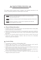
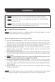
Important Safety Instructions Please save these instructions. This manual contains important safety, installation, and operating instructions for the inverter. The following symbols are used throughout the manual: WARNING CAUTION NOTE Indicates a potentially dangerous condition. Use extreme caution when performing this task. Indicates a critical procedure for safe and proper operation of the inverter. Indicates a procedure or function that is important to the safe and proper operation of the inverter.
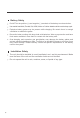
Battery Safety Do NOT let the positive (+) and negative (-) terminals of the battery touch each other. Use sealed Lead-Acid, Flooded, Gel, AGM, Lithium or Calcium batteries which must be deep cycle. Explosive battery gases may be present while charging. Be certain there is enough ventilation to release the gases. Be careful when working with large lead acid batteries. Wear eye protection and have fresh water available in case there is contact with the battery acid.
General Information The Renogy PCL series inverter-chargers combine an inverter and battery charger with an automatic transfer switch into one complete system. Featuring a 3-stage battery charging mode when connected to utility AC power, the PCL series inverter-charger can meet powerful demand needs as well as charge your battery bank. As a power supply, it is capable of producing cleaner, smoother, and more reliable electricity for a user's electronic needs. Take full advantage of the multiple features.
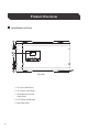
Product Overview Identification of Parts 3 4 2 5 1 Top view 1. AC Input Cable Entry 2. AC Output Cable Entry 3. Wired Remote Control Cable Entry 4. LCD Panel and Buttons 5.
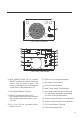
6 Left View (Covered) 10 12 9 8 11 14 13 15 18 16 7 17 Left View (Uncovered) 6. Main ON/OFF Switch: This is a simple ON/OFF switch to be able to control the inverter with the plate in place. The wiring is connected to the Terminal Block on the inside of the plate seen in 13. 10. Rj45 Port for Future Development 7. DC Negative Battery Terminal 14. Dry Contact Relay Port: NC, C, NO ports for connecting generators and making use of the Auto-Gen Start feature. 8.
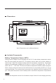
Dimensions Note: Dimensions are in millimeter[inches] Included Components Battery Temperature Sensor (BTS) Renogy inverter chargers come equipped with a 9.9 ft / 3 meter battery temperature sensor that will help prolong the battery life. The battery sensor allows the inverter charger to continuously adjust the charging voltage based on the battery temperature. The inverter charger will compensate charging with a factor of -0.5mV/C◦ per degree after 77F°/25C°, within -40C°/F° ~ 176F°/80C°.
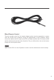
Wired Remote Control The wire remoted control for the inverter chargers gives users the opportunity to power on/off the inverter from a distance. Giving you approximately 16.4ft of distance, simply connect the cable to the RJ11 port on the PCL unit. Make sure both the PCL inverter model and the wired remote are both in the off position. The you will be able to turn on the inverter charger via remote power switch.
Installation WARNING CAUTION CAUTION Make sure inverter is in the off position before connecting anything. Do not over-torque or over tighten the terminals. This could potentially damage the unit. Refer to the technical specifications for max wire sizes on the controller and for the maximum amperage going through wires. Location Recommendations WARNING Never install the inverter in a sealed enclosure with flooded batteries. Gas can accumulate and there is a risk of explosion.
Sizing a Battery Bank Determine the amount of Watts (Amps * Volts) for the load, and how long the load needs to operate—each electrical appliance has technical specificationsindicating the watts, or the volts and amps required for operation. Estimate load run-time—Battery size depends on load watts and run-time. Most loads are not constant, so estimation is very important.
DC WIRING WARNING CAUTION NOTE NOTE WARNING The Renogy Pure Sine Wave Inverters are suitable for 12V battery bank systems ONLY. Not following the minimum DC requirement will cause irreversible damage to the unit. Be careful of the positive and negative poles. Reversing the poles might cause permanent damage to the inverter. It will surely blow the internal fuse. Damage to the Renogy inverters due to reverse polarity is NOT covered by warranty.
When installing DC cables, the following are recommendations: 1. Battery positive and negative cables should be as close to the battery as possible to minimize voltage loss and other possible effects. 2. Tie, tape, or twist cables together to reduce self-inductance. 3. Install all overcurrent devices on the positive cable.
1.Remove the AC Terminal block 2.Make note of the AC output terminals from left to right (Ground, Live, Neutral) and the AC Input terminals from left to right (Neutral, Live, Ground).
NOTE The input terminals of the inverters have large capacitors connected to them. Once a positive and negative wire are connected to the terminals, it will complete the circuit, and commence drawing a heavy current momentarily. As a result, there may be a sparking occurring even if the inverter is in the off position. To minimize sparking, it is recommended that the user have the appropriate size wire feeding into the inverters and/or install an external fuse leading into the inverter charger.
Automatic Transfer Relay The PCL inverter chargers are equipped with a 30A transfer relay switch that switches between Inverter and Standby mode depending on availability of AC input power. If AC is present, the transfer relay bypasses up to 30A of the incoming AC power through the inverter to power the AC loads on the inverter’s output. In the event AC power gets disconnected, the inverter will power the loads through the battery bank.
Operation Upon successful connection of a 12V deep cycle battery bank, flip the inverter power to the ON position. NOTE NOTE Upon successful connection of a 12V deep cycle battery bank, flip the inverter power to the ON position. The unit may also be powered on by the wired remote control. Function Keys Exit setting mode, go back to main menu Cycle through the menu Cycle through the menu 1. Hold down to enter Parameter setting menu. 2.
INPUT OUTPUT V AC V 100% 25% Input Volts AC / Output Volts AC BATT OUTPUT V VA 100% 25% Battery Volts DC / Load Volts AC BATT OUTPUT V W 100% 25% Battery Volts DC / Output Watts 17
BATT OUTPUT V % 100% 25% Battery Volts DC / Output Load % BATT OUTPUT V Hz 100% 25% Battery Volts DC / Output Frequency INPUT OUTPUT V AC Hz 100% 25% Input Frequency / Output Volts AC 18
INPUT V AC A 100% 25% Input Volts AC / Input Amps TEMP OUTPUT C O V 100% 25% Inverter Temperature Celsius / Output Volts AC 100% 25% Inverter Version Number 19
05 Setup Battery Type The PCL inverter charger series is fully programmable. The minimum programming needed to get started would be to set the battery type. Press and hold the parameter setting key to enter parameter setting mode. Use the arrow keys to go to Program 05. Use the following table to set the appropriate battery type based on the boost voltage and float voltage that has been preset. NOTE The PCL series is only compatible with 12V battery banks.
05 Custom Battery Type /User Mode If the preset battery options are not compatible with your system, you will need to custom the charging by following the next steps. 1. Set the battery type to b-0. By default this unit is preset to boost at 14.3V and Float at 13.7V. Program Number Description For Charging to be accurate, Temperature Sensor must be connected. Parameter Setting User-defined ( default fast V 14.3, If User-Defined is selected ,user can set the Floating V 13.7) battery type in program94 2.
b.Once finished, go to Program 27 to set the battery low voltage recovery charge. This will be the voltage that the battery discharges to before the inverter-charger charges the battery to the predetermined maximum charging voltage Program Number Description Battery low voltage open charging(for lithium battery) 27 Parameter Setting If User-defined is selected in program 94,this program can be set up.Setting range is from 12.0V to 14.0V for 12V BATT V 4.If choosing a custom non-lithium battery (i.e..
LED Indicator AC/INV Green CHG Green FAULT Red Parameter Solid Output is powered by an AC source in line Flashing Output is powered by battery or in invert mode Solid Battery is fully charged Flashing Battery is charging Solid Fault occurred Flashing Warning conditions has occurred Function Keys Exit setting mode, go back Cycle through the menu Cycle through the menu 1. Hold down to enter Parameter setting menu. 2.
AC INPUTBATT KW VA %C Hz ERROR ERROR OUTPUTBATTLOAD KW VA % Hz CHARGING <12.0V 12.0.V-12.5V 12.5V-13.0V >13.
<10.3V 10.3V 10.8V 10.8V~11.3V >11.3V <10.9V 10.9V 11.4V 10.9V~11.9V >11.9V <11.2V 11.2V 11.7V 11.7V~12.2V >12.2V OVER LOAD Indicates the load level by 0-24%, 25-49%, 50-74% and 75-100%.
Programmable Features The PCL inverter charger series is fully programmable. You may change the respective parameter by going to the Program Number listed below Function Keys Exit setting mode, go back to main menu Cycle through the menu Cycle through the menu 1. Hold down to enter Parameter setting menu. 2.
The following steps need to be taken to properly set the inverter charger to Battery Priority (SbU) 1. Press and hold the Enter key to enter the setting screen. 2. Press the down arrow key until setting 01 is shown. 3. Press and hold the Enter key until the setting starts flashing, press the up or down arrow key to select SbU. Press and hold the Enter key to save the setting. 4. Disconnect the inverter charger from the AC source/shore power. 5.
04 Power Saving Mode Power saver function is designed to conserve battery power when AC power is not or rarely required by the loads. In this mode, the inverter pulses the AC output looking for an AC load (i.e., electrical appliance). Whenever an AC load (greater than 50 watts) is turned on, the inverter recognizes the need for power and automatically starts inverting and output goes to full voltage.
11 Maximum Utility Charging The PCL inverter chargers can operate like battery chargers converting incoming AC power into DC recharging power. The 2000W has a 65A max while the 3000W has a 75A max adjustable battery charging. The default is the maximum value (65A-2KW, 75A-3KW), with a 5A minimum. 11 12 Low Battery Voltage Setpoint The purpose of this setpoint is to protect the batteries from being over discharged. It assumes that Battery Priority is set on Program 01.
Alarm Parameters: Inverter Charger Failure (Low-voltage The buzzer will keep beeping Shutdown, High-voltage Shutdown, Overheating Protection, Overload Protection) Pressing Function Keys The buzzer will beep for 0.5s Working Mode Transfer The buzzer will beep for 0.5s Overheating/Overload Alarm The buzzer will beep for 0.3s every 1s Low-voltage/High-voltage Alarm The buzzer will beep for 0.2s every 0.
25 Record Fault Code The PCL inverter will demonstrate the fault code. 25 26 Boost Charging Refer to Program 5 for modifying this setting. NOTE This setting will not be modifiable if users choose a pre-set battery voltage. Bulk charging voltage(C.V voltage) If User-defined is selected in program94,this program can be set up. Setting range is from program 94 BATT V 26 Maximum charging voltage for Lithium battery. When the voltage reaches the set voltage, charging will stop.
The default setting is 10.0V. Setting range is from 10.0V to 12.0V with increments of 0.1V. This setting must be at least 0.5V lower than setting #98 Low Battery Alarm. 29 BATT V 93 Input Frequency Range The factory default frequency for inverters is 60Hz. Normally, manufacturers build electrical devices for a certain amount of Current, Voltage and Hertz (Cycles) which is mentioned on the name plate. The Current is dependent of the Voltage and the Hertz supplied to an electric motor or appliance.
When dry contact switch from NC to NO, battery voltage arrive to setting voltage, dry contact point switch to NC. This setting can not be than fast charge voltage.higher setting range is from 13.0V to 15.5V for 12V Increment of each click is 0.1V for 12V 95 BATT V 96 Low Voltage Trip for Dry Contacts The PCL inverter charger series have functions to automatically start and stop a generator for supplementing charge.
98 Low Battery Voltage Alarm Users can select to have the PCL inverter-charger sound an alarm at a programmable battery voltage. This will need to be a higher value than Program 29 Low DC Cut-off Voltage as it will warn users that the battery is discharging before ultimately disconnecting. 98 Low voltage battery alarm The default is 10.5V. The setting range is 10.5V-12.5V with increments of 0.1V. This setting will be at least 0.
Battery Charging Stages Bulk Stage: The charger will supply constant current until the battery voltage reaches the boost voltage. The software will calculate the time charging began up until the battery voltage reaches 0.3V below the boost voltage. It uses this time to as T0 and T0×10 = T1. Boost Stage: The charger will supply constant voltage and reduce the current slowly through this stage. The charger will stay in this stage until T1 has run out. After this time the charger will enter the float stage.
Fault / Warning Codes NOTE The following fault codes will have a caution symbol when experiencing the fault Warning Code Warning Event Icon On Battery over voltage Battery low voltage Inverter over temperature Inverter overload 88 Transformer phase reversal 89 Frequency is out of range NOTE 02 The following will experience an error display as well as the fault code Heat sink over temperature ERROR Battery voltage is too high ERROR Battery voltage is too low 06 99 ERROR Output short circu
Technical Specifications Model R-INVT-PCL1-20111S R-INVT-PCL1-30111S Inverter Specifications Rated Output Power 2000W 3000W Surge Power (1 second) 6000W 9000W Surge Power (3 seconds) 3000W 4500W Surge Power (10 seconds) 2400W 3600W Nominal output Voltage RMS 120 VAC ( 100 ~ 120VAC, 5V intervals 50HZ ± 0.3HZ or 60HZ ± 0.
Model R-INVT-PCL1-20111S R-INVT-PCL1-30111S Transfer Switch Specifications Transfer Time ~ 10ms Line Mode Efficiency Transfer Relay Rating > 95% 30A Maximum Bypass General Specifications Battery Types GEL, AGM, SLA, FLD, CAL, LI, USER Operating Temperature Range 0~40°C/0~104°F -30~70°C/-22~158°F 0% ~ 95% Storage Temperature Humidity Noise Dimensions Weight Certifications <50dB 510 x 285 x 193 mm / 20.1 x 11.2 x 7.6 in 51.1 lbs / 23.2 Kg 63.5 lbs / 28.8 Kg ETL listed to CSA Standard C22.2 No.
RENOGY.COM Renogy reserves the right to change the contents of this manual without notice. US 2775 E Philadelphia St, Ontario, CA 91761, USA 909-287-7111 www.renogy.com support@renogy.com CN 苏州高新区科技城培源路1号5号楼-4 JP https://www.renogy.jp supportjp@renogy.com CA https://ca.renogy.com supportca@renogy.com AU https://au.renogy.com supportau@renogy.com UK https://uk.renogy.com supportuk@renogy.com DE https://de.renogy.com supportde@renogy.com 400-6636-695 https://www.renogy.cn support@renogy.