REGO DC-DC Battery Charger 12V 60A VERSION A0 input DC-DC Battery Charger output USER MANUAL
Applicability The user manual applies to the following product: z REGO 12V 60A DC-DC Battery Charger (RBC1260DO-12B) Disclaimer z Renogy makes no warranty as to the accuracy, sufficiency, or suitability of information in the user manual because continuous product improvements are going to be made. z Renogy assumes no responsibility or liability for losses or damages, whether direct, indirect, consequential, or incidental, which might arise out of the use of information in the user manual.
Table of Contents Important Safety Information ..................................................................................................05 Symbols Used ....................................................................................................................05 General Safety Information ................................................................................................05 Introduction .............................................................................................
Inter-Device Communication ..............................................................................................39 Monitoring Device Communication ....................................................................................42 Operation ................................................................................................................................47 Selecting the Battery Type .................................................................................................
Important Safety Information Symbols Used General Safety Information Important Safety Information The user manual provides important installation, operation, and maintenance instructions for REGO 12V 60A DC-DC Battery Charger. Please read the user manual carefully before installation and operation and save it for future reference.
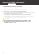
Important Safety Information Symbols Used General Safety Information z Keep the battery charger out of the reach of children. z Please wear proper protective equipment and use insulated tools during installation and operation. z Do not touch the connector contacts when the charger is working. z Please remove all connections before maintenance or cleaning. z Do not dispose of battery charger as household waste. Please use recycling channels in accordance with local, state, and federal regulations.
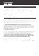
Introduction Introduction Key Features Four Charging Stages Lithium Activation Introduction Introduction The Renogy REGO DC-DC Battery Chargers save on installation time than traditional chargers. The pioneering bidirectional charging technology not only provides the most effective way to charge your house batteries from the starter battery on the go but also recharges and maintains your starter battery when the house batteries are full.
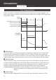
Introduction Introduction Key Features Four Charging Stages Lithium Activation Four Charging Stages REGO 12V 60A DC-DC Battery Charger has a four-stage battery charging algorithm for a rapid, efficient battery charging. They include Bulk Charge, Boost Charge, Float Charge, and Equalization Charge.
Introduction Introduction Key Features Four Charging Stages Lithium Activation voltage set point. Once the battery is fully charged, there will be no more chemical reactions and all the charge current would turn into heat or gas. In this case, the DC-DC Battery Charger will reduce the voltage charge to smaller quantity, while lightly charging the battery. The purpose for this is to offset the power consumption while maintaining a full battery storage capacity.
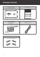
Package Contents Package Contents REGO 12V 60A DC-DC Battery Charger x 1 Quick Guide x 1 REGO DC-DC Battery Charger 12V 60A VERSION A1 input input DC-DC Battery Charger DC-DC Battery Charger output output QUICK GUIDE Renogy Temperature Sensor x 1 (Model: RTSCC) Screws x 4 ST6.3x1.
Optional Accessories Optional Accessories Starter Battery Fuse (90A) as input Auxiliary Battery Fuse (80A) as output The battery fuses will protect battery charger, wires and batteries from overcurrent. Fuse Cable The wire is designed with two sections of copper rings, thus enabling the battery charger to function as an external fuse. Battery Voltage Sensor (Model: RVSCC) The charging voltage of the battery charger is affected by the length and size of the wire.
Product Overview Product Overview 1 2 3 4 1 input DC-DC Battery Charger output DC-DC Battery Charger DC-DC Battery Charger input 5 6 No. 12 CAN output 7 Part 8 9 IGN 10 BVS 11 No.
Wiring Diagram DC-DC B attery Ch arger Wiring Diagram input + output + Positive Starter Battery or DC Alternator Auxiliary Battery System Negative 13
Recommended Cable Sizing Recommended Cable Sizing Model REGO 12V 60A DC-DC Battery Charger (RBC1260DO-12B) Cable Input Output Cable Length (ft) / (m) Recommended Cable Size 0 to 10ft / 0 to 3m 6AWG 11 to 20ft / 3 to 6m 6AWG 21 to 30ft / 9 to 6m 4AWG 0 to 10ft / 0 to 3m 8AWG 11 to 20ft / 3 to 6m 6-8AWG 21 to 30ft / 9 to 6m 6AWG NOTE z The cable specifications listed above account for critical, less than 3% voltage drop and may not account for all configurations.
Preparation Components & Tools Checking the Battery Charger Checking Auxiliary Battery Automobile Alternator Check Preparation Components & Tools CAUTION z The adapter cable used in this manual can be made by yourself or purchased from Renogy official website according to the names in Recommended Components.
Preparation Components & Tools Checking the Battery Charger Checking Auxiliary Battery Automobile Alternator Check Battery Scenario B: Normal Battery Kit Normal Battery with +/- Bolts Battery Adapter Cables (input / output) ( Anderson PP75 to Ring Terminal Adapter Cable ) + - Required Tools Wrench (14mm) 14mm 5 6 10mm 10mm 4 14mm 3 10mm 16 Measuring Tape 14mm Wrench (10mm) Insulation Tape
Preparation Components & Tools Checking the Battery Charger Checking Auxiliary Battery Automobile Alternator Check Checking the Battery Charger D C -D C B at te ry C ha r ge r 1. Please inspect the battery charger for any visible damage including cracks, dents, deformation, and other visible abnormalities. All connector contacts shall be clean, dry, and free of dirt and corrosion. inp ut outp ut WARNING z Do not use the battery charger if it has any visible damage. 2.
Preparation Components & Tools Checking the Battery Charger Checking Auxiliary Battery Automobile Alternator Check 3. Measure the length of the cables connecting to the battery and solar panel so they can be connected to the battery charger. DC-DC Battery Charger NOTE z If the Battery Adapter Cable or Solar Panel Extension Cable is not long enough, you can use more extension cables or reselect the position where the battery charger needs to be secured.
Preparation Components & Tools Checking the Battery Charger Checking Auxiliary Battery Automobile Alternator Check CAUTION z If you replace your battery with a new one, please dispose of the used battery through the specified recycling channel according to the local, state, and federal laws and regulations. WARNING z Do not use the battery charger if it has any visible damage. z Do not touch the exposed electrolyte or powder if the battery housing is damaged.
Preparation Components & Tools Checking the Battery Charger Checking Auxiliary Battery Automobile Alternator Check 1. Locate your main vehicle battery/starter battery. 2. Start the engine, ensuring any fans, radio, and lights. are turned off. Leave the engine running for around 5 to 10 minutes. CK A LO RT TA ON C S C 3. Read the voltage of the main vehicle battery. + - For traditional alternators, the DC voltage is around 14.4V. For smart alternators, the DC voltage is around 12.5V to 13.5V.
System Diagram Battery Scenario A: REGO Battery Kit Battery Scenario B: Normal Battery Kit System Diagram Battery Scenario A: REGO Battery Kit Using the System Combiner Box Accessory Set Starter Battery or DC Alternator Battery Fuse (90A) attery Cha rger + DC-DC B - input output REGO 4 Ports 400A System Combiner Box REGO 12V 400Ah Lithium Iron Phosphate Battery Positive Negative 21
System Diagram Battery Scenario A: REGO Battery Kit Battery Scenario B: Normal Battery Kit Using Positive/Negative Busbars Accessory Set Starter Battery or DC Alternator Battery Fuse (90A) attery Cha rger + DC-DC B - input output Battery Fuse (80A) Positive/Negative Busbars REGO 12V 400Ah Lithium Iron Phosphate Battery Positive Negative 22
System Diagram Battery Scenario A: REGO Battery Kit Battery Scenario B: Normal Battery Kit Battery Scenario B: Normal Battery Kit Starter Battery or DC Alternator attery Cha rger + DC-DC B - Battery Fuse (90A) input output Battery Fuse (80A) + + - - Normal Battery with +/- Bolts (12V) Positive Negative 23
Battery Charger Wiring Battery Charger Wiring DC-DC Battery Charger NOTE z Please refer to the “Recommendations of Wire Diameters and Fuses” in this manual, and select the satisfied cables according to the usage. z Please make sure that the connections of the Anderson connectors are tight and secure. REGO Battery Kit input input Normal Battery Kit output output 1. For the Output terminal, align the Battery Adapter Cable’s Anderson PP75 connectors to the correct orientation and polarity.
DC-DC Battery Charger Battery Charger Wiring input input output 4. For the Input terminal, align the Battery Adapter Cable’s Anderson PP75 connectors to the correct orientation and polarity. DC-DC Battery Charger 5. Bind the Anderson PP75 connectors by sliding the side grooves. input 6. Insert the Anderson PP75 connectors into the Input terminal.
Auxiliary Battery Wiring Battery Scenario A: REGO Battery Kit Battery Scenario B: Normal Battery Kit Battery Indicator Auxiliary Battery Wiring NOTE z Identify the polarity (positive and negative) on the cables used for the batteries. A reverse polarity contact may damage the unit. z Please ensure that the Anderson connectors are fully seated and/or the ring terminals are securely connected.
Auxiliary Battery Wiring Battery Scenario A: REGO Battery Kit Battery Scenario B: Normal Battery Kit Battery Indicator █ Using Battery Adapter Cable ( Anderson PP75 to Ring Terminal Adapter Cable ) NOTE z Select the appropriate wrench according to positive/negative wire fixing bolt specifications of the system hub. input 1. Attach the ring terminal of the negative Battery Adapter Cable (output) to the negative battery bolt and tighten it with a wrench. DC-DC Battery Charger output Output - input 2.
Auxiliary Battery Wiring Battery Scenario A: REGO Battery Kit Battery Scenario B: Normal Battery Kit Battery Indicator Using Positive/Negative Busbars Accessory Set NOTE z Please select the applicable wrench according to wire fixing bolt specifications of Positive/ Negative Busbars. WARNING z Please select the right size of positive/negative sink according to the maximum continuous charging/discharging current of the battery operation.
Auxiliary Battery Wiring Battery Scenario A: REGO Battery Kit Battery Scenario B: Normal Battery Kit input DC-DC Battery Charger output Output - Battery Indicator 3. Attach the ring terminal of the negative Battery Adapter Cable (output) to the negative battery bolt and tighten it with a wrench. + - input 4. For your safety, it is recommended to use a battery fuse (80A).
Auxiliary Battery Wiring Battery Scenario A: REGO Battery Kit Battery Scenario B: Normal Battery Kit Battery Indicator Battery Scenario B: Normal Battery Kit NOTE z Please select the appropriate wrench according to the battery positive/negative wire fixing bolt specifications. input DC-DC Battery Charger output Output - - + - 12 12 input 2. For your safety, it is recommended to use a battery fuse (80A).
Auxiliary Battery Wiring Battery Scenario A: REGO Battery Kit Battery Scenario B: Normal Battery Kit Battery Indicator Battery Indicator Once the battery wiring is completed correctly and the battery is turned on, the battery charger’s Battery indicator lights up green. D C -D C B at te ry C ha rg er When the battery is performing normally, the Battery indicator may not light up. This means the battery charger needs troubleshooting. For details, contact our customer service through renogy.
Input Wiring Input Wiring REGO 12V 60A DC-DC Battery Charger can be directly connected to the vehicle’s starter battery (12V). NOTE z Please select the appropriate wrench according to the battery positive/negative wire fixing bolt specifications. z Please ensure that the ring terminals are securely connected. WARNING z Identify the polarity (positive and negative) on the cables used for the batteries. A reverse polarity contact may damage the unit. 1.
Input Wiring input 3. For your safety, it is recommended to use a battery fuse (90A). Connect the positive Battery Adapter Cable (output) to one end of the battery fuse, and then connect the other end to the positive bolt of the battery. DC-DC Battery Charger output Input + + + 4. Attach the ring terminal of the positive Battery Adapter Cable (input) to the positive terminal of the starter battery.
Input Wiring WARNING z Identify the polarity (positive and negative) on the cables used for the batteries. A reverse polarity contact may damage the unit. Alternator Recommendation Check your alternator and identify the number of terminals. Most alternator will have 3 wires connected (BAT+, BAT-, and IGN). The table below shows an example alternator terminal, and may not match your application. Refer to your vehicle’s documentation and part for actual wiring.
Input Wiring Engine Bay Fuse Block Recommendation Review your vehicle’s fuse layout to identify a fuse location that is live when the vehicle is running with the alternator. Key positions in the ignition are typically lock, accessory, on, and start. Off position where no accessories will work, and steering is also likely locked. LOCK ACCESSORY Accessories are given power such as radio and some other small electronics. ON Turns on all your electronics.
Mounting Mounting NOTE z Please make sure that the battery charger is installed firmly to prevent it from falling off. 1. Place the battery charger against a flat surface and secure it with included screws.
Temperature Sensor Temperature Sensor The temperature sensor can detect the battery’s temperature and update it to the battery charger for charging voltage calibration. This ensures the battery charger (with operating temperature range from -20°C to 60°C or -4°F to 140°F) can charge the battery normally. CAUTION DC-DC Battery Charger z Do not use the temperature sensor on a LiFePO4(LFP) battery which comes with a battery management system(BMS). 1.
Voltage Sensor (Optional) Voltage Sensor (Optional) The Battery Voltage Sensor is the perfect solution by providing an accurate battery voltage to the battery charger and allowing it to adjust the charging stage precisely resulting in overall extension of your battery life. NOTE z The voltage sensor ring is M8 (Approx. 5/16”). If the battery bolt size is small, please use a gasket to fix it to prevent it from falling off.
Communication Inter-Device Communication Monitoring Device Communication Communication The REGO DC-DC Battery Charger can communicate with other REGO devices and monitoring devices, enabling safe operation, smart control, remote monitoring, and programmable settings. Inter-Device Communication Depending on the installation condition, the RV-C communication connections between the battery charger and other REGO devices can be established with backbone or daisy chain topology.
Communication Inter-Device Communication Monitoring Device Communication Communication z Different drop sockets are used on the RV-C bus by different RV manufacturers. Please select the Drop Plugs that match the drop sockets for the inter-device communication connections. If you are not sure about the Drop Plug selection, please check with the RV manufacturer. This User Manual takes the Mini-Clamp II plug (4-pin) as an example. z Different Drop Plugs follow different pinouts.
Communication Inter-Device Communication Monitoring Device Communication D C -D C B ry at te er rg C ha IGN BVS BTS 4. Connect either of the CAN Communication Ports of the battery charger and other REGO devices to the drop sockets on the drop tap with the Drop Cables. NOTE z Different drop taps are used on the RV-C bus by different RV manufacturers. This User Manual takes the 4-socket drop tap as an example. CAUTION z If unable to locate the drop taps, please contact the RV manufacturer for help.
Communication Inter-Device Communication Monitoring Device Communication D C -D C B ta te ry ha rg e C 2. Plug the Termionator Plugs (sold separately) into the free CAN Communication Ports on the first and last REGO devices. r D C -D C B at te r y C ha rg er IGN IGN BVS BVS BTS BTS Monitoring Device Communication The battery charger can be connected to monitoring devices through both short-range and long-range connections.
Communication Inter-Device Communication Monitoring Device Communication Long-Range Monitoring If long-range communication and programming are required, connect the battery charger to Renogy ONE through Bluetooth or wires, and the Renogy ONE to the DC Home app through Wi-Fi. Recommended Accessories Renogy ONE NOTE z Please make sure that the Renogy ONE is powered on before the connection. INFO z Please read the user manual of Renogy ONE at renogy.com before the connection.
Communication Inter-Device Communication Monitoring Device Communication █ Wired connection Recommended Accessories(Backbone Topology) RJ45 Plug to Bare Wires Drop Cable Drop Plugs Backbone Topology 1 2 345 6 78 43 21 C -D C D B ry at te er rg ha C IGN BVS Split Joint Pilers 1. Crimp the Drop Plug (not included) on the Drop Cable (not included) with the Split Joint Pilers. The white green CAN_H wire goes to pin 2 and the white orange CAN_L wire goes to pin 3. Leave pin 1 and pin 4 empty.
Communication Inter-Device Communication Monitoring Device Communication 2. Monitor and program the complete system on Renogy ONE or the DC Home app. C -D C D B at te r y er rg ha C IGN BVS BTS 12V Power Supply Recommended Accessories(Daisy Chain Topology) LP16 Plug (7-Pin) to RJ45 Communication Adapter Cable 1. Remove the Terminator Plug from the REGO device at either end of the daisy chain. C -D C D Daisy Chain Topology ry te at B er rg ha C IGN BVS BTS C -D C D 2.
Communication Inter-Device Communication Monitoring Device Communication 3. Bind Renogy ONE to the DC Home app. Monitor and program the complete system on the Renogy ONE or the DC Home app.
Operation Selecting the Battery Type Battery Charging Parameters User Mode Operation Selecting the Battery Type The battery charger is simple and easy to use. The knob with 5 gears makes the selection of battery type more convenient. The default battery type of the battery charger is AGM/SLD. After the wiring of the battery charger output is completed, please manually set the battery type according to needs. WARNING z Refer to battery manufacturer technical specifications when choosing a preset battery.
Operation Selecting the Battery Type Battery Charging Parameters User Mode 4. If the auxiliary battery is Lithium Battery, turn the knob to LI. input DC-DC Battery Charger output input 5. If multiple parameters of the battery need to be programmed, turn the knob to USER to enter custom mode. DC-DC Battery Charger output CAUTION z After entering the custom mode, you need to use the DC Home app to program the battery parameters. Please refer to the User Mode of this chapter for details.
Operation Selecting the Battery Type Battery Charging Parameters User Mode Battery Charging Parameters WARNING z Before modifying battery parameters, please check the table below first. Incorrect parameter setting will damage the device and void the warranty. Battery Type AGM/SLD GEL FLOODED LI (LFP) USER (Default) USER (Recommended) OverVolts Shutdown 16.0V 16.0V 16.0V 16.0V [16.0V] — OverVolts Limit 15.5V 15.5V 15.5V 14.8V [15.5V] Equalization Voltage — — — 14.8V — 14.6V 9.
Operation Selecting the Battery Type Battery Charging Parameters User Mode User Mode WARNING z Before modifying battery parameters in User mode, please check the table below and consult the battery manufacturer to check whether modification is allowed. Incorrect parameter setting will damage the device and void the warranty. Maximum Charging Current Equalization Voltage REGO 12V 60A DC-DC Battery Charger Max.
Operation Selecting the Battery Type Battery Charging Parameters User Mode NOTE z Make sure Bluetooth is turned on. z Please scan the QR Code on the last page of the User Manual to download the DC Home app. z DC Home illustrations in the User Manual are for reference only. Please follow the instructions based on the current app version. 1. Open the DC Home app. Tap “+” to search for new devices. 2. Tap “Confirm” to add the newly found device to the device list. 3.
Operation Selecting the Battery Type Battery Charging Parameters User Mode 4. Tap “•••” in the upper right corner. 5. Tap “Settings” to open the mode selection interface. 6. In this interface, you can customize multiple parameters of the battery. When the parameters are modified, “Setting Success” appears on the interface, indicating that the parameter setting is completed.
Charging Logic Charging Logic REGO 12V 60A DC-DC Battery Charger can be charged in two methods. It can be directly connected to the 12V DC Alternator or the 12V starter battery. Different charging methods adapt to more modification situation of users. The charger also supports parallel charging by using two 800W battery chargers to charge the auxiliary battery at the same time. █ Working conditions Starter Battery Voltage Alternator Type Cut-in Cut-off Smart Alternator >12.5V, for 15 seconds <11.
Charging Logic (2) If the voltage is greater than 12V, the auxiliary battery will stop charging the starter battery and activate the standby state. 2. Traditional Alternator: The auxiliary battery will charge the starter battery only when the voltage of the auxiliary battery is greater than 12.7V. The auxiliary charger will charge the starter battery for 1min and then stop charging for 30s. During this period, the battery charger will test the voltage of the starter battery automatically.
LED Indicators Battery status Fault status LED Indicators Battery status Indicator Color Green Status Description a. Auxiliary battery full ON b. Float charge c. Standby state Green / Blue Flashing (1s interval) The charging battery is charging the Auxiliary battery OFF Not charging ON The charging battery is charging the starter battery Fault status Indicator Color / Red Red Red Status Description OFF The charger is working properly a. Auxiliary battery short circuit ON b.
Troubleshooting Troubleshooting Fault Solid Red Solid Red Slow Flashing Red Description Auxiliary battery short circuit Internal overtemperature of the charger Recommendations 1. Please check if the positive and negative terminals of the life battery are connected correctly. 2. If the fault message persists, disable the charger and contact RENOGY. 1. Please check the environment around the charger to ensure that enough space is left for heat dissipation. 2.
Maintenance Inspection Cleaning Storage Maintenance Inspection For optimum performance, it is recommended to perform these tasks regularly. z Check the appearance of the battery charger to make sure it is clean and dry. z Ensure the battery charger is installed in a clean, dry and ventilated area. z Ensure there is no damage or wear on the cables. z Ensure the firmness of the Anderson connectors and check if there are any loose, damaged or burnt connections.
Emergency Responses Fire Flooding Smell Noise Emergency Responses In the event of any threat to health or safety, always begin with the steps below before addressing other suggestions. z Immediately contact the fire department or other relevant emergency response team. z Notify all people who might be affected and ensure that they can evacuate the area. WARNING z ONLY perform the suggested actions below if it is safe to do so. Fire 1. Disconnect all cables connected to the charger. 2.
Technical Support Technical Support For additional support, contact the Renogy technical support team through renogy.com/ contact-us. Have the following information available when contacting Renogy. z Owner name z Contact information z Order number z Purchase channel z Serial number z Brief description of the issue Visit renogy.com to find relevant documentation or get more support via "Contact Us". US www.renogy.com CN www.renogy.cn UK uk.renogy.com CA ca.renogy.com AU au.renogy.com JP renogy.
Technical Specifications Technical Specifications Parameter Value Model RBC1260DO-12B System Voltage 12V Input Voltage 10V to 16V DC Output Voltage 10V to 16V DC Alternator Input Traditional Alternator: 13.5V to 16VDC Smart Alternator (Euro 6): 12.
Dimensions Dimensions 350mm [13.78in] input DC-DC Battery Charger output 264.5mm [10.41in] 289.5mm [11.4in] 186.67mm [7.35in] CAN IGN BVS BTS CAN input output 102mm [4.02in] 213mm [8.39in] CAUTION z Dimensional tolerance of ± 0.
FCC Statement This device complies with Part 15 of the FCC Rules. Operation is subject to the following two conditions: (1) This device may not cause harmful interference. (2) This device must accept any interference received, including interference that may cause undesired operation. This equipment has been tested and found to comply with the limits for a Class B digital device, pursuant to Part 15 of the FCC Rules.
RENOGY.COM Visit renogy.com to find relevant documentation or get more support via "Contact Us". Renogy reserves the right to change the contents of this manual without notice. Manufacturer: RENOGY New Energy Co.,Ltd Address: No.66, East Ningbo Road Room 624-625 Taicang German Overseas Students Pioneer Park JiangSu 215000 CN EC REP eVatmaster Consulting GmbH Battinastr.30 60325 Frankfurt am Main, Germany contact@ evatmaster. com Manufacturer: RENOGY New Energy Co.,Ltd Address: No.