
User Manual

05
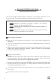
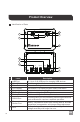
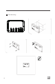
Identification of Parts
Product Overview
#
Label Description
1
2
1
4
8
7
6
2
3
5
9
10
USB Port 5V, Up to 2.4A USB port for charging USB devices.
Select Button Cycle through the interface
3
Enter Button Parameter Setting button
4
LCD Display Blue Backlit LCD displays system status information
5
Mounting Holes diameter holes for mounting the controller
6
PV Terminals Positive and Negative PV Terminals
7
Battery Terminals Positive and Negative Battery Terminals
8
RS232 Port
BVS
9
10
Temperature
Sensor Port
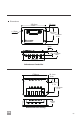
PV+ BATT+ BATT-
RS232
Temp.
Sensor
Batt.
Remote
PV-
EN
Battery Temperature Sensor port utilizing data for accurate
temperature compensation and charge voltage adjustment.
Battery Voltage Sensor port for measuring the battery
voltage accurately with longer line runs.
Communication port for connecting monitoring accessories
such as Bluetooth, requires a separate purchase.