MONITORING SCREEN FOR PGH INVERTER SERIES Version 1.
Important Safety Instructions Please save these instructions. This manual contains important installation and operation instructions for your Renogy monitoring screen. Please review and observe these instructions and keep them located near the monitoring screen for further reference. The following symbols are used throughout the manual to indicate potentially dangerous conditions or important safety information. WARNING CAUTION NOTE Indicates a potentially dangerous condition.
General Safety Information Installation and wiring must comply with the Local and National Electric Codes (NEC) and must be done by a certified technician. Read all the instructions and cautions in the manual before beginning the installation. There are no serviceable parts for this inverter. Do NOT disassemble or attempt to repair the monitoring screen. Make sure all connections going into and from the inverter are tight.
Monitoring Screen Safety The monitoring screen is designed for indoor/compartment installation. DO NOT expose it to direct sunlight, rain, snow, moisture, or liquids of any type. DO NOT puncture, drop, crush, burn, penetrate, or strike the monitoring screen. DO NOT open, dismantle, or modify the monitoring screen. The monitoring Screen is only compatible with Renogy PGH Inverter Series. DO NOT attempt connecting the monitoring screen to other inverters or systems.
Table of Contents Important Safety Instructions 01 General Information 05 Product Overview 06 Identification of Parts 06 Dimensions 07 Installation 09 Operation 15 LCD User Interface: Overview 15 Voltage (V) 16 Current (A) 16 Watts (W) 16 Frequency (Hz) 17 Error Code 17 Normal / ECO Mode 18 LED Indicators 19 Troubleshooting 19 Technical Specifications 21 04
General Information The RMS-PGH is a high precision meter designed for PGH series pure sine wave inverters. Featuring a backlit display and flush-mountable, it is engineered for an aesthetically clean and professional look on RVs or camper walls. Utilize the 2-key input to easily navigate through your system information as well as identify any error codes. In addition, use the power button to manually shut down the inverter at your convenience.
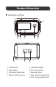
Product Overview Identification of Parts ON ELEC ⑤ ERR RMS-PGH ① ② ⑦ ③ ⑧ ① LCD Screen ② Input/output ③ Parameter Switch Key ④ Main On/Off power key ④ ⑥ ⑨ ⑤ LED Status Lights ⑥ Front Cover Plate ⑦ Mounting Holes ⑧ RJ45 Communication Port ⑨ RJ12 Communication Port 06
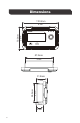
Dimensions 110.0mm 4.3in 70.0mm 2.8in ON RMS-PGH 87.5mm 3.4in 58.5mm 2.3in 31.8mm 1.3in 19.5mm 0.
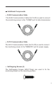
Additional Components RJ45 Communication Cable The RJ45 Communication Cable (5m/16.4ft) is used to connect the monitoring screen to the "COMM" port for data transmission. RJ12 Communication Cable The RJ12 Communication Cable (5m/16.4ft) is used to connect the monitoring screen to the "REMOTE" port for power supply. Self-tapping Screws (4) The Self-tapping Screws (M2.9*13mm) are used to fix the monitoring screen on the mounting surface.
Installation WARNING BEFORE drilling, make sure there are no electrical component or other obstacles that may interfere with installation on the other side of the mounting surface. CAUTION Before installation, check to make sure the power is working properly. Resolve any issues before installation of monitoring screen and cable. The RMS-PGH requires a flush mount installation. The RMS-PGH’s faceplate will be flush with the mounting surface and the body of the meter.
Mounting the Monitoring Screen 1. Remove the snap-fit Front Cover Plate from the monitoring screen. 2. Use the monitoring screen as a template to mark the screw holes and trace the cut-out area on the mounting surface with a pencil. 3. Cut out a rectangle area for the monitoring screen on the mounting surface with a jigsaw. You may also use the cut out dimension specified after Step 2. 4. Pre-drill four screw holes on the mounting surface with a drill. 5.
2 3 11
4 Cutout Dimensions (L x H x W): 86.7 x 58.02 x 19.
6 7 13
Connecting to the PGH Inverter series The RMS-PGH will operate when the PGH Inverter is in the ON or REM position. Only in the REM position, will the RMS-PGH be able to manually turn the inverter ON/OFF in addition to monitoring the inverter. In order to read the parameters of the inverter correctly, 1. The switch must be in the ON or REM position and the COMM port correctly connected to the RJ45 cable. 2.
Operation NOTE The communication cables need to be connected correctly in order to read the parameters of the inverter correctly.
Voltage (V) Input The voltage indicates the DC Input voltage of the battery bank. Volts will be in DC Output The voltage indicates the AC Load Voltage. Volts will be AC Current (A) Input - Output The real-time current flowing from the inverter to the AC appliances. Current will be AC amps Watts (W) Input - Output The real-time watts flowing from the inverter to AC Appliances.
NOTE The RMS-PGH will not calculate the watts below 100 watts. Instead the following code will display depending on the watts Output W AC Watts < 50W W 50W < AC Watts < 100W Frequency (Hz) The monitoring screen will only be able to monitor the working mode. To change the output frequency the DIP switch needs to be physically selected on the unit BEFORE turning on the inverter.
The error code indicates potentially abnormal conditions of the inverter. During normal operation this will not display on the screen. Error Code Parameter 01 Battery Under-Voltage Warning 02 Battery Over-Voltage Warning NOTE The error code will flash, and the inverter will beep the alarm. Upon the battery reaching the error state, the monitor screen will shut down just like the inverter. Normal / ECO Mode The PGH inverter features a power saving mode (ECO) to conserve battery power.
LED Indicators LED ON Color Behavior Parameter Solid The inverter is powered on in normal mode Slow Flash The inverter is powered in ECO mode detecting a load to power >50W Green ELEC Yellow Solid GFCI Trip ERR Red Solid Fault Troubleshooting Indicator Potential Issue Error Code 01, ERR LED Lit Error Code 02, ERR LED Lit 19 Input voltage below 11V Troubleshoot Use a multimeter to check the voltage of the battery bank. Disconnect any loads and charge the battery back up.
Monitor screen shutdown Inverter under-voltag e protection Use a multimeter to check the voltage of the battery bank to make sure you're above 11V. Disconnect loads if any and make sure you're only using 12V battery bank systems. Inverter over-voltag e protection Use a multimeter to check the voltage of the battery bank to make sure you're below 15V. Disconnect loads if any and make sure you're only using 12V battery bank systems.
Technical Specifications Electrical Specifications Model RMS-PGH Supply Voltage 5VDC Supply Current 30mA Power Consumption <1W Operating Temperature Range -4℉~113℉ / -20℃~45℃ Voltage Accuracy ±0.1V Current Accuracy ±0.1A Certification FCC Part 15 Class B, CE, RoHS Mechanical Specifications 21 Communication Port RJ45, RJ12 Display Backlit LCD User Interface 2 key input, 1 main power switch Mounting System Wall Mount Dimension 2.8*4.3*1.3 inch 70*110*31.8 mm Weight 0.
FCC Compliance: This device complies with Part 15 of the FCC Rules. Operation is subject to the following two conditions: (1) this device may not cause harmful interference, and (2) this device must withstand any interference received, including interference that may cause undesired operation. NOTE This equipment has been tested and found to comply with the limits for a Class B digital device, pursuant to part 15 of the FCC Rules.
RENOGY.COM Renogy reserves the right to change the contents of this manual without notice. US 2775 E Philadelphia St, Ontario, CA 91761, USA 909-287-7111 www.renogy.com support@renogy.com CN 苏州高新区科技城培源路1号5号楼-4 JP https://www.renogy.jp supportjp@renogy.com CA https://ca.renogy.com supportca@renogy.com AU https://au.renogy.com supportau@renogy.com UK https://uk.renogy.com supportuk@renogy.com DE https://de.renogy.com supportde@renogy.com 400-6636-695 https://www.renogy.cn support@renogy.