
Installation Guide


6
4.2 Top Down Clamps
Clamps are an approved method of mounting for Renogy modules. A
clamp holds two modules in a row. The centerline of the clamps must be
in-line with the module mounting holes and installed according to code.
4.3 Grounding
The frame of the PV module, as well as any exposed non-current carrying
metal parts of fixed equipment that can be energized must be grounded to
avoid electrical shock. Renogy recommends grounding all PV module
frames to ensure the voltage between the conductive equipment and the
earth ground is zero in all circumstances.
Appropriate grounding consists of using an appropriately sized EGC or
racking system that can be used for integrated grounding. Renogy panels
implement a coated aluminum frame for corrosion resistance. The frame
rails have pre-drilled holes marked with the grounding sign. Do not drill
additional holes into the frame rails.
Note that the stainless steel washer is used between the grounding
wire and the module frame. This is for avoiding corrosion due to
dissimilar metals.
The module frame must be properly grounded (refer to NEC clause
250). The grounding wire must be properly fastened to the module
frame to assure good electrical contact. Use the recommended type,
or an equivalent, connector for this wire.
If the support frame is made of metal, the surface of the frame must
be electroplated and have excellent conductivity.
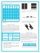
We recommend the lay-in lug (Cat. No. GBL4-DBT; rated for
600Volts; company: ILSCO; UL number is E34440)when
grounding. First strip 16mm insulating jacket from the end of the
ground wire (4-14 STR.) carefully to avoid nicking or cutting
conductors, insert the wire into the slot of the lug (see the picture),
and screw down the slotted screw.
Next, assemble the recommended ILSCO grounding lug to the
aluminum frame using stainless steel M3 or M5 screw and hardware
as shown below. Note: there are two different size grounding holes,
the smaller of which is being phased out.
Further, buildup of hardware for mounting the grounding lug are the
same—except for the M3 screw, an added flat washer is mounted
directly under the M3 screw head. The star washer is fitted directly
under the grounding lug and makes electrical contact by penetrating
the anodized coating of the aluminum frame, The screw assembly is
further fitted with a flat washer, then a split lock washer and finally a
nut to secure the entire assembly, as shown. Recommended torque
of M3 or M5 screw assembly is 0.8NM or 1.5 NM.
4.4 Module Dimensions
The modules will be mounted using the mounting holes (on the short
side of the aluminum frame), closest to the edges.