The Traveler SeriesTM : Adventurer 30A PWM Flush Mount Charge Controller w/ LCD Display 2775 E. Philadelphia St., Ontario, CA 91761 1-800-330-8678 Version: 3.
Important Safety Instructions Please save these instructions. This manual contains important safety, installation, and operating instructions for the charge controller. The following symbols are used throughout the manual: WARNING: Indicates a potentially dangerous condition. Use extreme caution when performing this task.
Be careful when working with large lead acid batteries. Wear eye protection and have fresh water available in case there is contact with the battery acid. Over-charging and excessive gas precipitation may damage the battery plates and activate material shedding on them. Too high of an equalizing charge or too long of one may cause damage. Please carefully review the specific requirements of the battery used in the system.
Table of Contents General Information ......................................................................................................................................... 4 Included Components .................................................................................................................................... 6 Identification of Parts ..................................................................................................................................... 7 Installation ......
General Information The Adventurer is an advanced charge controller for off-grid solar applications. Integrating highly efficient PWM charging, this controller increases battery life and improved system performance. It can be used for 12V or 24V battery or battery bank. The controller is embedded with selfdiagnostics and electronic protection functions that prevent damages from installation mistakes or system faults.
Bulk Charge: This algorithm is used for day to day charging. It uses 100% of available solar power to recharge the battery and is equivalent to constant current. Boost Charge: When the battery has charged to the Boost voltage set-point, it undergoes an absorption stage which is equivalent to constant voltage regulation to prevent heating and excessive gassing in the battery. The Boost time is 120 minutes.
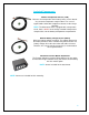
Included Components Remote Temperature Sensor (TS-R) Measures the temperature at the battery and uses this data for very accurate temperature compensation. The sensor is supplied with a 6.6ft cable length that connects to the charge controller. NOTE: The Adventurer comes equipped with a temperature sensor, but it is ONLY for the charge controller’s temperature compensation, not the battery’s temperature compensation. Remote Battery Voltage Sensor (RBVS) Measures battery voltage accurately.
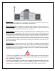
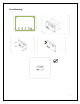
Identification of Parts 4 5 6 7 7 Key Parts 1. 2. 3. 4. 5. 6. 7.
Installation WARNING: Connect battery terminal wires to the charge controller FIRST then connect the solar panel(s) to the charge controller. NEVER connect solar panel to charge controller before the battery. CAUTION: Do not over-torque or over tighten the screw terminals. This could potentially break the piece that holds the wire to the charge controller. CAUTION: Refer to the technical specifications for max wire sizes on the controller and for the maximum amperage going through wires.
Flush Mounting: 9
Surface Mount Attachment The charge controller can also be mounted on a flat surface using the Adventurer Surface Mount Attachment. In order to properly mount the charge controller, steps 1 and 2 for the flush mount option can be followed. However, there is no need to cut a section of the wall considering the charge controller can now be mounted on a flat surface using the attachment. Mark and drill holes using the four pan head Phillips screws that are provided specifically for the surface mount option.
2.
3.
4. Insert Battery Voltage Sensor block terminal and connect wires (POLARITY SENSITIVE) If unscrewing the wires from the Temperature Sensor Block and Battery Voltage Sensor Block, make sure to not mix up the wires and terminal blocks. Doing so will result in irreversible charge controller damage.
Operation After connecting the battery to the charge controller, the controller will turn on automatically. Assuming normal operation, the charge controller will cycle through different display. They are as follows: Parameter Display PV Array Voltage PV 0.0 V Charging Current PV 0.0 A Generated Energy PV 0.0 kWh Battery Voltage BATT 0.0 V Battery SOC% BATT 0.0 % Temperature BATT 0.0 F° The Adventurer is an easy to use controller requiring minimal maintenance.
ENTER Cycles backwards through the different select screens & Customize some parameters on the charge controller Change the Parameters Simply hold the “ENTER” button for approximately 5 seconds until the display flashes. Once flashing, then press “SELECT” until the desired parameter is reached and press “ENTER” one more time to lock in the parameter. NOTE: The screen must be at the appropriate interface in order to change the specific parameter. 1.
System Status Icons Icon Behavior Constant: System is normal, but it is not charging Charging: The bars will be sequencing indicating the system is charging. Constant: The battery is at full charge. Flashing: The battery is overvoltage. Flashing: The battery is under voltage. System Status Troubleshooting Indicator Description Troubleshoot Battery over voltage Flashing Flashing Use a multi-meter to check the voltage of the battery.
Maintenance For best controller performance, it is recommended that these tasks be performed from time to time. 1. Check that controller is mounted in a clean, dry, and ventilated area. 2. Check wiring going into the charge controller and make sure there is no wire damage or wear. 3. Tighten all terminals and inspect any loose, broken, or burnt up connections Fusing Fusing is a recommendation in PV systems to provide a safety measure for connections going from panel to controller and controller to battery.
Technical Specifications Description Parameter Nominal Voltage Rated Charge Current Max. PV Input Voltage Equalization Voltage 12V / 24V Auto Recognition 30A 50 VDC Sealed: 14.6 V; Gel: None; Flooded: 14.8 V (x2 / 24V) Boost Voltage Float Voltage Under Voltage Self-consumption Temperature Compensation Coefficient Operating Temperature Storage Temperature Enclosure Terminals Weight Sealed: 14.4 V; Gel: 14.2 V; Flooded: 14.6 V (x2 / 24V) 13.
Low Voltage Disconnect Discharging Limit Voltage Equalization Duration Boost Duration 11.1 V 11.1 V 11.1 V 10.8 V 10.8 V 10.
Renogy reserves the right to change the contents of this manual without notice.