The Traveler Series: Wanderer RENOGY 30A PWM Charge Controller Manual 1 2775 E. Philadelphia St., Ontario, CA 91761 1-800-330-8678 Version: 2.
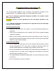
Important Safety Instructions Please save these instructions. This manual contains important safety, installation, and operating instructions for the charge controller. The following symbols are used throughout the manual: WARNING: Indicates a potentially dangerous condition. Use extreme caution when performing this task.
Battery Safety Do NOT let the positive (+) and negative (-) terminals of the battery touch each other. Use only sealed lead-acid, flooded, or gel batteries which must be deep cycle. Explosive battery gases may be present while charging. Be certain there is enough ventilation to release the gases. Be careful when working with large lead acid batteries. Wear eye protection and have fresh water available in case there is contact with the battery acid.
Table of Contents General Information ............................................................................................................................................ 5 Optional Components ........................................................................................................................................ 7 Identification of Parts .........................................................................................................................................
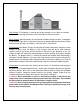
General Information The Wanderer (CTRL-WND30) is an advanced charge controller for off-grid solar applications. Integrating highly efficient PWM charging, this controller increases battery life and improved system performance. It can be used for a 12V battery or battery bank. The controller is embedded with self-diagnostics and electronic protection functions that prevent damages from installation mistakes or system faults.
Bulk Charge: This algorithm is used for day to day charging. It uses 100% of available solar power to recharge the battery and is equivalent to constant current. Boost Charge: When the battery has charged to the Boost voltage set-point, it undergoes an absorption stage which is equivalent to constant voltage regulation to prevent heating and excessive gassing in the battery. The Boost time is 120 minutes.
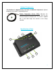
Optional Components *The Wanderer is shipped with by itself with no additional components. Optional components that require a separate purchase: Remote Temperature Sensor (TS-R): Measures the temperature at the battery and uses this data for very accurate temperature compensation. The sensor is supplied with a 6.6ft cable length that connects to the charge controller.
Key Parts 1. 2. 3. 4. 5. 6. 7. Battery Select Button Battery Select Indicator Battery Indicator PV Indicator Remote Temperature Sensor Adapter (Requires separate purchase) PV Terminals Battery Terminals Installation WARNING: Connect battery terminal wires to the charge controller FIRST then connect the solar panel(s) to the charge controller. NEVER connect solar panel to charge controller before the battery. CAUTION: Do not over-torque or over tighten the screw terminals.
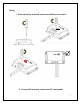
Wiring 1. Unscrew battery terminals and connect battery connections 2.
3.
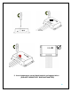
Operation After connecting the battery to the charge controller, the controller will turn on automatically. Operation of this controller is very simply. Users set the battery type, and leave the rest of the work to the charge controller. Setting Battery Type Simply hold the gray button for approximately 7 seconds until the LED flashes.
Set Battery Type Sealed Gel Flooded LED Indicators The Wanderer is a simple to use controller requiring little to no maintenance. Users can be informed about the charge controller’s status based on the LED indicators at the PV and Battery levels. The following chart goes into further detail regarding the Wanderer’s indicators.
System Status Troubleshooting Description Battery is low-voltage Battery is over-voltage PV is over-voltage Battery is over-heating Troubleshoot Use a multi-meter to verify the rated battery voltage. Disconnect any loads connected to the battery to allow it to charge. Use a multi-meter to check the voltage of the battery. Make sure the battery voltage is not exceeding the rated specification of the charge controller. Disconnect battery. Use a multi-meter to check the voltage of the panels.
2. Check wiring going into the charge controller and make sure there is no wire damage or wear. 3. Tighten all terminals and inspect any loose, broken, or burnt up connections Fusing Fusing is a recommendation in PV systems to provide a safety measure for connections going from panel to controller and controller to battery. Remember to always use the recommended wire gauge size based on the PV system and the controller. NEC Maximum Current for different Copper Wire Sizes AWG 16 14 12 10 8 6 4 2 0 Max.
Technical Specifications Electrical Specifications Description Parameter Nominal Voltage 12 VDC Rated Charge Current 30A Max. PV Input Voltage 25 VDC Self-Consumption <10mA High Voltage Disconnect 16V Over-Voltage Reconnect 15V Low Voltage Disconnect 11.1V Low Voltage Reconnect 12.6V 12V Under Voltage Warning 12.2V Under Voltage Recover ≤15V Charging Limit Voltage Sealed:14.6V; Flooded: 14.8V; Gel: NO Equalization Voltage Sealed: 14.4V; Flooded: 14.6V; Gel: 14.2V Boost Voltage 13.
Low Voltage Disconnect Discharging Limit Voltage Equalization Duration Boost Duration 11.1 V 11.1 V 11.1 V 10.8 V 10.8 V 10.8 V ----2 hours 2 hours 2 hours 2 hours 2 hours Mechanical Specification Description Temperature Compensation Working Temperature Storage Temperature Max Gauge Size Weight Dimensions Enclosure Parameter -3mV/°C/2V -30°C—45°C / -20°F—113°F -35°C—80°C / -31°F—176°F Up to #4AWG 0.29 kg / 0.65 lbs. 163.83 x 109.62 x 44.7mm 6.45 x 4.31 x 1.