DC-DC Multifunctional Charger Installation and Operating Manual
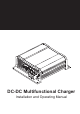
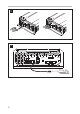
1 1 2 3 4 5 6 sensor 78 9 OUTPUT 10 OUTPUT S1 S2 S3 S4 S5 3
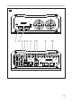
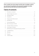
2 5 cm 5 cm 3 A 4 B
4 5
5 1. 3. 2.
Please read this instruction manual carefully before installation and first use, and store it in a safe place. If you pass on the product to another person, hand over this instruction manual along with it. Table of contents 1 Description of symbols . . . . . . . . . . . . . . . . . . . . . . . . . . . . . . . . . . . . . . . . . 8 2 General safety instructions. . . . . . . . . . . . . . . . . . . . . . . . . . . . . . . . . . . . . . . 8 3 Package includes . . . . . . . . . . . . . . . . .. . . . . .
Description of symbols 1 Description of symbols ! DANGER! Safety instruction: Failure to observe this instruction will result in fatal or serious injury. ! WARNING! Safety instruction: Failure to observe this instruction can result in fatal or serious injury. ! CAUTION! Safety instruction: Failure to observe this instruction can lead to injury. NOTICE! Failure to observe this instruction can cause material damage and impair the function of the product.
General safety instructions 2.1 ! ! General safety DANGER! • In the event of fire, use a fire extinguisher that is suitable for electrical devices. WARNING! • Only use the product as intended. • Ensure that the red and black terminals never come into contact with each other. • Disconnect the product from the battery – each time before cleaning and maintenance – before a fuse change (only by specialists) • If you disassemble the product: – Detach all connections.
General safety instructions 2.2 ! ! Safety when installing the product DANGER! • Never mount the product in areas where there is a risk of gas or dust explosion. CAUTION! • Ensure a secure stand! The product must be set up and fastened in such a way that it cannot tip over or fall down. NOTICE! • Do not expose the product to any heat source (such as direct sunlight or heating). Avoid additional heating of the product. • Set up the product in a dry location protected from splashing water. 2.
General safety instruction • Do not lay the cables so that they are loose or heavily kinked. • Firmly secure the cables. • Do not pull on the cables. 2.4 ! ! Safety when operating the product WARNING! • If the product is used in facilities with open lead acid batteries, the room must be well-ventilated. These batteries give off explosive hydrogen gas that can be ignited by sparks on electrical connections.
Package includes ! CAUTION! • When working on batteries, do not wear any metal objects such as watches or rings. Lead acid batteries can cause short circuits which can cause serious injuries. • Danger of explosions! Never attempt to charge a frozen or defective battery. In this situation, place the battery in a frost-free area and wait until the battery has adjusted to the ambient temperature. Then start the charging process. • Wear goggles and protective clothing when you work on batteries.
Accessories 4 Accessories Available as accessories (not included in the package): Description Ref. no. Temperature sensor TS-1 RNG-DCC-TS 5 Target group for this manual The chapter “Connect charging converter” on page 18 chapter is solely intended for qualified professionals who are familiar with the relevant VDE regulations. All other chapters are intended for the users.
Technical description ! 7 WARNING! Danger of explosions! • Do not charge batteries with a cell conclusion. The oxyhydrogen they produce can cause explosions. • Do not charge lead acid batteries in unventilated rooms. The oxyhydrogen they produce can cause explosions. • Do not charge NiCd batteries or non-rechargeable batteries with this device. The sleeves of these batteries can explode.
Technical description NOTE The individual values are found in chapter “Protective devices” on page 27. The battery charger can be adapted to different battery types via DIP switches. When a TS-100 temperature sensor is connected, the charging converter adjusts the charging voltage according to the measured temperature, see chapter “Technical data” on page 24. 7.1 Connections and controls Item in fig.
Technical description 7.2 Battery charging function The charging characteristics are referred to as IU0U characteristics. U/V I/A 1 2 3 U I U0 U 100 % I 10 % t 1: I phase (bulk) At the beginning of the charging process, the flat battery is charged with a constant current (100 % charge current) until the battery voltage reaches the charging end voltage. The charging current decreases when the battery has reached this charging level.
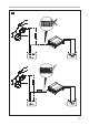
Mount charging converter 8 Mount charging converter 8.1 Tools required For the electrical connection you will need the following tools: • Crimping tool • 4 flexible connection cables: + and – for the starter battery, + and – for the body battery. 1 flexible signal cable for connection to D+ or the ignition. The required cross-section can be found in the table chapter “Connect charging converter” on page 19.
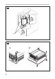
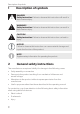
Connect charging converter 8.3 Charging converter NOTICE! Before drilling any holes, make sure that no electrical cables or other parts of the vehicle can be damaged by drilling, sawing, and filing. Pay attention to the distance specifications (fig. 2 , page 4). Mount the charging converter as shown (fig. 3 , page 4). 9 Connect charging converter ! WARNING! Do not reverse the polarity. Reverse polarity of the battery connections can cause injury and damage the device.
Connect charging converter Determine cable cross-section NOTE Keep the distance to the body battery as short as possible. The minimum cable cross-section depends on the maximum cable length: Cable length Minimum cable cross-section/Fuse 2.5 mm² / 30 A DCC-1212-20 DCC-1212-40 DCC-1212-60 9.1 4 mm² / 40 A 6 mm² / 60 A 10 mm² / 80 A to the starter battery ≤7 m ≤11 m ≤16 m – to battery structure ≤2 m ≤3.5 m ≤5 m – to the starter battery – ≤5.5 m ≤8 m ≤14 m to battery structure – ≤1.
Us e c hargi ng conve rter 10 Use charging converter 10.1 Switch charging converter on/off The charging converter turns on automatically as soon as it receives a positive control signal. The status LED glows blue. The charging converter switches off automatically when the control signal is no longer present. NOTE If the control signal of the charging converter is switched via the ignition, the starter battery can discharge if the engine is not started in a timely manner. 10.
Use charging converter Set float voltage You can use the DIP switches S3 and S4 toset the float voltage in the U phase (float). S3 S4 Float voltage 12 V ON ON 13. 8 V OF F ON 13. 5 V ON OFF OF F OFF 13. 2 V Set charging mode WARNING! Danger of explosions! Use only the charging mode appropriate for your battery type. If necessary inquire at a specialist workshop. ! You can set the charger mode using the S5 and sw itches.
Troubleshooting 12 ! Troubleshooting WARNING! Do not open the device. You risk exposing yourself to an electric shock by doing this. NOTE If you have detailed questions about the battery charger data, please contact the manufacturer (addresses on the back of the instruction manual). LED does not glow Check the electric connections. If you cannot find an error, contact customer service. 13 Warranty The statutory warranty period applies.
Technical data DCC-1212-20 Transformation: 12 V Input voltage range: 8 V – 16 V 20 A 40 A Charging voltage: Output: 60 A 13.2 V – 14.7 V 250W 500W Residual ripple of output voltage at rated current: 750W < 50 mV eff Efficiency up to: 90 % Idle power consumption: < 0.
Technical data Temperature compensation NOTE The temperature compensation is only effective if a RNG-DCC-TS temperature sensor is connected and the IU0U charging mode is selected.