
Installation Guide

75
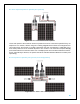
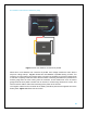
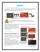
Please refer to Fig. 3. Each end of the battery tray cables should have a “ring terminal” type of
connector. These connectors make it easy to achieve a secure and strong connection. Once the
cables are connected and bolted down to the inverter, connect the black cable to the negative
post of the battery (-). Then, connect the red cable to the positive post of the battery (+). If
connecting to a battery bank, make sure that the black cable connects to the negative battery
post (-) at the end of the bank (opposite to the positive battery post as shown on Fig. 3). It is
recommended that a fuse be placed on the hot line (positive) between the battery and inverter.
Please refer to the owner’s manual for the proper wire gauge size and fuse ratings for each
inverter.
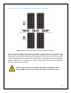
Ground!
The negative battery terminal and the chassis ground of the inverter should
be connected to a system ground. This is a safety measure to prevent
electrical shock!
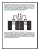
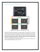
NOTE: The charge controller and the inverter should be connected to the same battery
terminals (same connecting points shown in Figure 10.2), no exceptions.
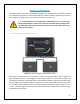
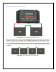
Step 3: Connecting electrical appliances to inverter
Caution!
Make sure the power load is within the rated power of the inverter. The start power
of the appliances should not exceed the peak power of the inverter.
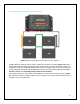
Once the devices are connected to the AC outlet, they are ready to be powered. When the inverter
is not in use, it is recommended that you turn off the inverter (switch in OFF position).
Figure 10.2 Inverter wiring diagram