
Instruction Manual


Instruction Manual Connect Radar 2022 Version 4.0 (GSD-100549)
Page 8
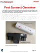
Setup
Open the Radar unit using the supplied key. (Figure 1)
The unit is supplied with the battery fitted.
Slide circuit board switch to ‘ON’ – the LED will be red. (Figure 2)
Pass your finger across the first beam and the LED will flicker repeatedly. (Figure 3)
Move your finger to the second beam within four seconds – the solenoid will self test to complete
check and the unit doors will close.
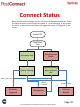
If the Control Panel is operating and in range of the Radar then the LED will flash purple to indicate
that the beacon signal is being received. After a short period* the LED will flash blue to indicate
that it has successfully joined the network. If however there is no beacon signal within range then
the LED will flash red at this point you should check that the Control Panel is powered otherwise
an additional Control Panel could be required on the site.
Once the Radar has joined the network, set the trigger by pressing the red door level down until it
is locked under the blue catch. (Figure 4 & 5)
Remove the blue safety pin from the CO
2
canister and ensure the canister is within its expiry date
before installing into the unit. (Figure 6 & 7)
Locate the canister in position – it should not need forcing. (Figure 8)
Close the unit securely. (Figure 9)
Note: If the canister resists the fittings, it is likely to be used and in need of disposal
* The time taken to join the network will depend on which radio scheme is being used i.e. which country the units are
deployed. In the European regions the join time should be less than 30 seconds but in North American and some
Asian regions where frequency hopping protocol is used it could take a few minutes to join the network.
Figure 1 Figure 2 Figure 3 Figure 4 Figure 5
Figure 6 Figure 7 Figure 8 Figure 9