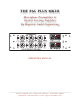
T H E PA L P L U S M K I I I M i c ro p h o n e P re a m p l i f i e r & O p t i c a l L e v e lin g A mp lifie r B y R eq ui site A u d io E n g in e e r in g OPERATOR’S MANUAL 2 1 7 5 G o o d y e a r Av e , S u i t e 11 0 , Ve n t u r a , C a l i f o r n i a 9 3 0 0 3 t e l e p h o n e : 8 1 8 . 4 3 7 . 0 7 7 9 • w w w. r e q u i s i t e A u d i o .
T H E PA L P L U S M K I I I TABLE OF CONTENTS INTRODUCTION 1 RECEIVING YOUR PAL 2 UNPACKING and INSPECTION: GENERAL NOTES 2 3 WARNING: 3 THIS SHIPMENT SHOULD INCLUDE: 3 SERVICING: 3 ENVIRONMENTAL CONSIDERATIONS: 3 FRONT PANEL CONTROLS (top row) 4 MIC/DI - LINE 4 MIC/DI GAIN 4 MIC/DI GAIN - OPERATIONAL NOTE: 4 HI-PASS FILTER 4 MIC/DI FEEDBACK 4 FRONT PANEL CONTROLS (top row continued) 5 -20dB PAD 5 OUTPUT LEVEL 5 +48V PHANTOM POWER 5 VU METER (upper meter) 5 VU ADJUST (s
T H E PA L P L U S M K I I I FRONT PANEL CONTROLS (bottom row) 6 HI-Z INPUT 6 LIMITER RESPONSE 6 LIMITER RESPONSE - OPERATIONAL NOTE: 6 MIC/LINK 6 FRONT PANEL CONTROLS (bottom row continued) 7 MIC/LINK - OPERATIONAL NOTE: 7 LIMITER FEEDBACK 7 LIMITER FEEDBACK - OPERATIONAL NOTE: 7 LIMITER LINK 7 FRONT PANEL CONTROLS (bottom row continued) 8 PEAK REDUCTION 8 PEAK REDUCTION - OPERATIONAL NOTE: 8 RATIO 10:1 / 3:1 8 GR TRK 8 PEAK REDUCTION METER (lower meter) 8 FRONT PANEL CALIBR
T H E PA L P L U S M K I I I STEREO ADJUST - CALIBRATION PROCEDURE (continued): 11 STEREO ADJUST - OPERATIONAL NOTE: 11 FRONT PANEL CALIBRATION POINTS (continued) 12 RESET STEREO ADJUST to higher sensitivity: 12 GR ZERO ADJUST 12 GR ZERO ADJUST - OPERATIONAL NOTE: 12 REAR PANEL (LEFT to RIGHT, top and bottom row) 13 GROUND 13 POWER SUPPLY INLET 13 AUDIO OUTPUTS 13 LIMITER LINK 13 TUBE CHANNEL 13 TUBE PLACEMENT and FUNCTION (left to right) 13 AUDIO INPUTS 13 OUTBOARD POWER SUPPLIE
T H E PA L P L U S M K I I I INTRODUCTION THANK YOU Thank you for using the PAL Plus MkIII and thereby making it a part of your art. The PAL Plus MkIII is the third generation of our PAL platform, now in it’s 13th year of production (2011). The original PAL (Preamp And Limiter) was introduced in 1998. and was based on a combination of our original Y7 microphone preamplifier and our L1 optical limiter. Within a year, the PAL was outselling all four versions of the Y7 and L1 combined.
T H E PA L P L U S M K I I I RECEIVING YOUR PAL UNPACKING and INSPECTION: Your shipment has been carefully inspected, checked and packaged at our company before being turned over to the carrier. We fully expect your PAL to arrive in your hands without having been harmed. However, at the point at which you do receive the product, it becomes your property. Therefore it is important that you carefully inspect the carton and it’s contents for any sign of physical damage which could have occurred in transit.
T H E PA L P L U S M K I I I GENERAL NOTES WARNING: DO NOT OPEN THE CABINET - RISK OF SEVERE ELECTRICAL SHOCK THIS SHIPMENT SHOULD INCLUDE: Model PAL Plus MkIII Model OPS-2D Solid-State Power Supply or RTS-2A Tube Power Supply PAL PLUS MkIII Operator’s Manual (this book) A.C. Cable (if shipped within the USA or Canada) SERVICING: The user should not attempt to service this unit beyond that described in this manual. Internal voltage can exceed 350 VOLTS D.C.
T H E PA L P L U S M K I I I FRONT PANEL CONTROLS (top row) MIC/DI - LINE This switch selects between the transformer balanced microphone input and the transformer balanced +4 line level input. The associated XLR connectors appear on the rear panel. MIC/DI GAIN Provides continuously variable gain of the microphone and direct instrument (DI) inputs. When used in conjunction with the output level control the input gain can be adjusted to create clean gain or to slightly overdrive the front end.
T H E PA L P L U S M K I I I FRONT PANEL CONTROLS (top row continued) -20dB PAD Applied only to the mic input before the microphone input transformer. If your source volume is extremely loud and/or you are using a highly sensitive microphone, the -20dB pad may be necessary to avoid distortion at the input. OUTPUT LEVEL MIC/DI INPUT MODE - This control should be adjusted for the desired output level (as indicated on the VU meter) after all other controls have been set.
T H E PA L P L U S M K I I I FRONT PANEL CONTROLS (bottom row) HI-Z INPUT The ¼” jack accepts single-ended outputs ranging from guitar pick-ups to active outputs from keyboards and drum machines. It provides a high load impedance of 1.5 meg ohms and will achieve a gain of 50dB. The MIC/LINE SWITCH must be in the MIC position for the Hi-Z input to operate.
T H E PA L P L U S M K I I I FRONT PANEL CONTROLS (bottom row continued) MIC/LINK - OPERATIONAL NOTE: A useful technique is to set one unit to normal compression levels and the second unit to very light, if any, compression and record each output to it’s own track. During mixdown, adjust the normally compressed track to normal levels as the main track and set the lightly or noncompressed track so that it “pokes through” during the heaviest compression of the first track.
T H E PA L P L U S M K I I I FRONT PANEL CONTROLS (bottom row continued) PEAK REDUCTION With PEAK REDUCTION set fully counter-clockwise, the MIC/DI input and LINE input exhibit no gain reduction and the PAL acts as a preamplifier or line amplifier. Turning PEAK REDUCTION clockwise will gradually initiate gain reduction for either the MIC/DI or LINE inputs, depending on which is selected. PEAK REDUCTION should be set for the desired amount of gain reduction as indicated on the (lower) GR meter.
T H E PA L P L U S M K I I I FRONT PANEL CALIBRATION POINTS CALIBRATION POINTS The PAL Plus MkIII has four points of calibration, all of which are found on the front panel. They are: • GR TRK - Gain Reduction Tracking is to synchronize the GR meter with the VU meter. • VU ADJUST - Calibrated for the VU meter (top) in dBu. Factory is 0dB = +10dBu. • STEREO ADJUST - Balance for stereo operation (2 units) and Peak Reduction sensitivity. • GR ZERO ADJUST - Gain Reduction meter adjustment to 0dBu (100%) at rest.
T H E PA L P L U S M K I I I FRONT PANEL CALIBRATION POINTS (continued) VU ADJUST - CALIBRATION PROCEDURE: VU ADJUST is calibrated in dBu. The trimmer has a wide enough range that “0” can be calibrated to virtually any reference level. Factory setting is 0dB = +10dBu (2.45VAC). • Set PEAK REDUCTION & LIMITER RESPONSE fully-counterclockwise. • Set OUTPUT LEVEL, LIMITER FEEDBACK fully-counterclockwise. • Allow 10 minutes system warm-up time and 1 minute rest from any peak reduction activity.
T H E PA L P L U S M K I I I FRONT PANEL CALIBRATION POINTS (continued) STEREO ADJUST - CALIBRATION PROCEDURE (continued): • Inject the +10dB 1-kHz tone to the LINE INPUT. Verify level using an external DMM or suitable meter. If your DMM has a dB function, select that. If not, set to A/C and read 2.45VAC across pins 2&3 of the OUTPUT XLR. • Adjust the OUTPUT LEVEL control until the VU METER (top meter) reads 0dB on both units. • Select LINK.
T H E PA L P L U S M K I I I FRONT PANEL CALIBRATION POINTS (continued) RESET STEREO ADJUST to higher sensitivity: • Inject a +10dB 1-kHz tone (both channels). Verify level using an external DMM or suitable meter. If your DMM has a dB function, select that. If not, set to A/C and read 2.45VAC across pins 2&3 of the OUTPUT XLR. • Select GR on the METER SELECT and observe that both VU METERs read 0dB. • Select MONO on PK REDUCTION (meter mode select).
T H E PA L P L U S M K I I I REAR PANEL (LEFT to RIGHT, top and bottom row) GROUND Banana Plug connection to CHASSIS Ground and/or CIRCUIT Ground is provided. Need for connection is unlikely, but can be useful in eliminating or finding source of hum, should hum exist. POWER SUPPLY INLET For connect to either of the REQUISITE OUTBOARD POWER SUPPLIES, models OPS-2 (SolidState Supply) or RTS-4 (All Tube Supply). When not connected to a power supply, be sure to use the security cap.
T H E PA L P L U S M K I I I OUTBOARD POWER SUPPLIES POWER SUPPLIES For the PAL Plus MkIII, and all Requisite mainframe audio processors, there is a choice of two different power supplies: • OPS-2D solid-state supply (1 to 2 channels) • RTS-4A all-tube supply (1 to 4 channels) Each supply is configured for the number of channels required for use a specific mainframe(s).
T H E PA L P L U S M K I I I WARRANTY For a period of 2 years after original purchase, Requisite Audio Engineering will, free of charge, repair this product if it fails due to defective materials or workmanship. This limited warranty is subject to the following limitations: • Units that are discovered to have been opened or tampered with will not be covered by this warranty.