
Specifications


RC3000/RC3050 INTERFACE SPECIFICATIONS
Research Concepts, Inc.
Shawnee, KS 66218-9680 USA
phone: (913) 422-0210 fax: (913) 422-0211
www.researchconcepts.com email: support@researchconcepts.com
Overview
The RC3000 Satellite Locator and RC3050 3-Axis Jog Controller are antenna controllers designed for use with elevation over
azimuth antennas on mobile satellite uplink vehicles (also referred to as satellite news vehicles - SNV's). The product has
also been adapted for use on flyaway systems. These microprocessor based controllers are housed in 2U rack enclosures
and interface directly with the antenna’s position sensors, limit switches and motors. The predecessor of these controllers
was the popular RC8097 Satellite Locator. This document describes the interface of the RC3000 and RC3050 controllers to
an antenna mount.
The RC3050 features a 2x16 liquid crystal display (LCD) and an 8 key keypad. The RC3050 can be supplied with an optional
hand-held remote control, (option RC3000HRC). The other option available for the RC3050 is auto-deploy and auto-stow
(option RC3050ASD). The auto deploy feature of the RC3050 allows the user to initiate an auto move that will raise the
antenna from the stow position to the vertical position. The auto stow feature automatically places the antenna in the stow
configuration.
The RC3000 calculates the antenna pointing solution given the vehicle latitude/longitude, vehicle heading, and satellite
longitude. (The pointing solution is the azimuth and elevation angles required to align the antenna with the desired satellite).
Once a pointing solution is available the controller can automatically position the antenna at the calculated azimuth and
elevation position. If the received signal (L band) or an analog voltage proportional to received signal strength is available the
controller will perform a search for the satellite. The RC3000 can obtain the vehicle heading from an optional flux gate
compass (designated RC3000FG) and the vehicle latitude and longitude from an optional GPS navigation receiver
(designated RC3000GPS). If the system does not include the optional flux gate and/or GPS sensors the user can manually
enter this data into the controller. The controller also allows the user to store a number of preset vehicle locations and
satellite longitude values. The RC3000CRC option adds support for RS-232 or RS-422 based serial communications using
the SA Bus protocol. The RC3000TRK option allows the RC3000 antenna controller to track inclined orbit satellites via step
track and memory track algorithms (the antenna must be fitted with azimuth and elevation type pulse position encoders for
inclined oribt tracking). The RC3000 also supports the RC3000HRC hand-held remote control.
Controller Types
The RC3000/RC3050 are currently available in two versions. Models with the ‘A’ suffix are designed for use with antennas
powered by low voltage (12 to 36 volts), high current (up to 12 amps) azimuth, elevation, and polarization DC motors. Models
with the ‘B’ suffix are designed for use with 90 volt (3/4 horsepower max) or 180 volt (1 ½ horsepower max) DC azimuth and
elevation motors (1 horsepower max) and 12 volt DC polarization control motors (400 ma max).
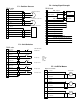
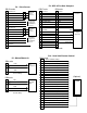
Schematics
Schematics that describe the controller’s motor, limit switch, position sensor, and accessory connections are included in the
appendix of this document.
Physical Characteristics
The RC3000 is designed for rack mounting. The dimensions are 19" x 3.5" x 17.5" (width x height x depth). The weight of
the RC3000A is 19 lbs. The RC3000B weighs 13lbs. The liquid crystal display (LCD) used with the unit is designed for
viewing from a 6 o'clock position. This means that the controller should be mounted above the operator’s eye level. An LCD
module optimized for a 12 o'clock viewing is also available.
The RC3000 enclosure is a standard rack mount chassis that occupies two rack units (2U). The controller is attached to the
panel via four (4) 10-32 screws. The distribution of weight within the controller requires that additional supports be provided
on either the back or sides of the controller enclosure. There are mounting points on the back and sides of the unit that can
accept 10-32 screws for securing the controller to these support structures. Note that the mounting points on the back of
the unit can also be used to attach cable strain relief straps. Locations of the additional enclosure mounting points is
detailed in the appendices of this document. The RC3000 must be supported from the rear.
Caution: RCI’s warranty does not cover damage to the controller due to inadequate support of the controller’s enclosure.
Cabling and Connectors
The only cables supplied with the unit are the AC line cord and the cables for the optional electronic compass and the GPS
receiver. All other cables must be supplied by the customer. A kit is available that contains all mating connectors. The kit
part number is FP-RC3K-CN-SET.