© 2008 Climate Automation Systems. All Rights Reserved. No part of this document may be photocopied, reproduced, stored in a retrieval system, or transmitted, in any form or by any means whether, electronic, mechanical, or otherwise without the prior written permission of Climate Automation Systems. No warranty of accuracy is given concerning the contents of the information contained in this publication.
Table of Contents 1 About this Guide ............................................................................................................................ 4 Audience .........................................................................................................................................4 Scope ..............................................................................................................................................4 Typographical conventions .......................
1 About this Guide This guide provides the instructions for installing and configuring Climate Automation Systems’ ENV climate control system. Audience This guide is intended for control contractors and mechanical contractors who install the components of the ENV climate control system including sensors and field wires. This guide assumes that you have some knowledge of basic low-voltage electrical wiring.
2 Overview of the System ENV is an energy management system that controls, manages, and monitors all aspect of a building’s environment. ENV is the first system of its kind to take intelligent climate control technologies and bring them to the residential and commercial market.
Prerequisites to installation Before you begin installation of the ENV climate control system, ensure the following are available: • an active external network connection • a router Installation Guide Page 6 of 20 Copyright 2008
3 Installing the Input/Output Module The ENV climate control system uses one or more input/output modules to interface with the climate control devices. Currently, the following Modbus-compatible DataNab input/output modules are certified for use with the ENV system: Module Analog Inputs Ai8_R13 81 AiO8 81 Ai32 321 Analog Outputs 84 Digital Inputs Digital Outputs Pulse Counter Comment 8 132 Yes3 A total of 8 universal inputs (analog, digital, or counter - max.
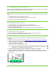
To connect power: 1. Make sure that the power source is off. 2. Connect the power wires to the module’s lower power terminals labeled 24VAC and . If using a DC power supply, connect the positive (+) wire to the 24VAC terminal and the negative (-) wire to the terminal. Caution: When wiring an Ai8_R13, make sure you connect power to the correct terminals. DO NOT connect to the upper terminals labelled POWER. Note: When using more than one module, you can daisy-chain the power wiring between modules. 3.
4 Installing the VLinx Serial Server The preferred PC to I/O module communication option requires a VLinx serial server. This section will guide you through installing the Ethernet to RS485 serial server.
Installation Guide Page 10 of 20 Copyright 2008
5 Installing Thermostats Include a communicating thermostat as part of the system when managing a typical forced air heating and cooling system. You can also use a communicating thermostat to control a radiant heat zone where traditional readout and manual setpoint adjustment is still desired at that location. Installing a communicating thermostat Communicating thermostats provide a way for the controlling computer to manage traditional forced air thermostats through a browser interface.
6 Communication Wiring After you install the various components of the ENV climate control system, you must set up the communication wiring so the components can communicate with the PC. To connect communication wiring: 1. Connect the VLinx converter to the network through a router or hub using a standard network cable. 2.
7 Wiring Equipment to the I/O Module Use a maximum wire size of 18AWG for wiring inputs and outputs. A 22AWG wire is the recommended size for inputs. If you must run analog signal wiring a long distance or through areas with electrical interference, use shielded wire. The shield should be connected to ground only at the panel end.
3. Connect digital input wiring as follows: 4. If the input is DC volts or milliamps, remove the module cover and set the configuration jumper for the input to indicate the type of input used. Make sure the jumper is positioned correctly for each input, as follows: Note: The default jumper setting is THERM (thermistor or dry contact).
3. To use the Ai8_R13 to drive high voltage loads (120VAC or greater), use an external load relay to separate the high voltage from the I/O module. Connect the wiring for driving a pump or heater as follows: 4. An alternate method requires no 12-24 volts external volts for the coil. By using an RIB21CDC or similar relay (available from Kele at www.Kele.com), the 2 low voltage control wires can be connected directly to the contact output of the A8_R13.
The AiO8 only provides a 0-10 volt DC output: The AiO8 always requires an external 12VDC relay to switch any load as it only outputs a 0-10 volt signal. The power for the relay comes from the AiO8.
When using an external 12 volt DC relay, the energize voltage must be10 volts or less. The coil impedance must be greater than 500 ohms. An RIBTU1C (single pole double throw) or RIBTU2C (double pole double throw) relay is an ideal external relay for use with the AiO8 I/O module as it can handle loads of 10 amps resistive or 1/3 HP motor at 240 volts AC. Kele is a good source for this item at www.Kele.com.
Wiring analog outputs You can wire analog outputs to the AiO8 DataNab module. Use analog outputs to control proportional type devices such as a valve, a variable speed pump, or a damper. Note: The standard analog output signal of an AiO8 I/O module is 0-10V. This signal can be converted to 0-20mA with an associated load resistor sized to provide 20mA at 10V. To wire analog outputs: 1. Be sure the I/O module power is off before wiring any outputs. 2.
8 Supported Sensors and Control Devices This section identifies the various sensors and control devices you can use with Climate Automation Systems’ ENV climate control system. Sensor/ Device Description Part Number Source I/O Module Modbus module with 8 channel analog inputs and 13 relay outputs Ai8_R13 http://www.datanab.com/controllers/ Ai8_R13.htm I/O Module Modbus module with 8 channel analog inputs/ analog outputs AiO8 http://www.datanab.com/controllers/ AiO8.
Thermocouple probe High pressure sensors for mounted NPT security TC-NPT http://www.omega.com/ppt/pptsc.as p?ref=TC-NPT Thermocouple with protection head Industrial thermocouples with protection heads Various http://www.omega.com/ppt/pptsc.as p?ref=NB1-ICIN_INDUST_TC Temperature transmitters Converts thermocouple or RTD signals into a 4 to 20 mA dc signal output TX90A Series http://www.omega.com/ppt/pptsc.