
Install Instructions

69-0874—3 2
DEFINITE PURPOSE (DP) CONTACTORS
Home and Building Control
Honeywell Limited-Honeywell Limitée
155 Gordon Baker Road
North York, Ontario
M2H 2C9
Helping You Control Your World
69-0874—3 J.S. Rev. 5-96 Printed in U.S.A
Home and Building Control
Honeywell Inc.
1985 Douglas Drive North
Golden Valley, MN 55422
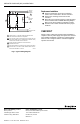
L2
L1
1
1
POWER SUPPLY. PROVIDE OVERLOAD PROTECTION
AND DISCONNECT MEANS AS REQUIRED.
THE CONTROL CIRCUIT INCLUDES LINE VOLTAGE OR LOW
VOLTAGE POWER SUPPLY (DEPENDING ON MODEL USED),
CONTROLLER AND/OR SAFETY DEVICES.
QUICK-CONNECT TERMINALS FOR ACCESSORY
CONNECTIONS ONLY.
FOR REPLACEMENT OF SINGLE POLE CONTACTORS WITH
TRICKLE HEAT, A SUITABLY SIZED JUMPER WIRE SHOULD
BE PLACED BETWEEN L1 AND T1.
2
M8731A
TO
CONTROLLED
LOAD
2
3
4
3
4
TO
CONTROL
CIRCUIT
SINGLE
PHASE
POWER
3
T2T1
Replacement Installation
쐃 Remove and identify contact and coil leads to
assure correct connection to the new contactor.
쐇 Remove the mounting screws from the old
contactor.
쐋 Mount the new contactor using the screws provided.
Some models include a 138550 Mounting Adapter
Plate for use when replacing competitive controls.
쐏 Reconnect the contact and coil leads to the proper
terminals.
CHECKOUT
Always conduct a thorough checkout when installation is
complete. Restore power supply and operate the contactor
and controlled equipment to assure the contactor pulls in
when the coil is energized and the controlled equipment
operates as intended.
Fig. 2. Typical wiring diagram.