
Install Instructions
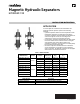
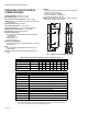

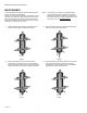
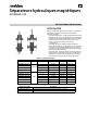
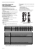
Table Of Contents

MAGNETIC HYDRAULIC SEPARATORS
3 33-00541EF—01
OPERATING SPECIFICATIONS
(FLANGED VERSION)
Temperature Range: 32-266 °F (0-130 °C)
Max. Working Pressure: 145 psi. (10 bar)
Max. Pressure of Air Vent Operation: 72 psi. (5 bar)
Fluids Used: Water, glycol-based solution (max. 50 % glycol
concentration)
Separator Connections: ASME 150 lb. flange
Air Vent Valve Connection: 1/2 in. ISO228
Discharge Valve Connection: 1in.
Separator Body: FE360 varnished steel
Automatic Air Vent Valve:
Body and Cap: ASTM B124 UNS C37700 (CW617N EN
12165) brass
O-Ring: EPDM
Shutter Spring: Inox
Internal Float: TPX
Drain Ball Valve: ASTM B124 UNS C37700 (CW617N EN
12165) brass
Insulation:
Shell: Polypropylene
Thickness: 0.78 in. (20 mm)
Density: 0.001 lb/in
3
(30 kg/m
3
)
Thermal conductivity: 0.039 W/m K
Fire Reaction (DIN 4102): Class B2
Magnet: AlNiCo (AlNiCo magnet provides higher operating
temperature and does not corrode.)
Fig. 2. Dimensions (flanged models). See Table 5.
Table 5. Dimensions for Flanged Hydraulic Separator (in inches). See Fig. 2.
E
F
D
C
A
B
M38527
Model Number
Size in
inches A B C D E F
HYDROSEP-105-F/U 2 36.5 12 11 13.5 13 7.1
HYDROSEP-106-F/U 2-1/2 41.2 12.8 14.2 14.2 14.1 8.3
HYDROSEP-107-F/U 3 47.5 14.4 17.3 15.8 17.7 10.2
HYDROSEP-108-F/U 4 52 15.4 19.7 17 19.7 12.4
HYDROSEP-109-F/U 5 58.3 15.7 23.6 19 21.7 14.4
HYDROSEP-110-F/U 6 66.1 17.7 27.6 20.9 23.6 15.6