
Install Instructions
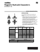
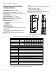

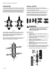
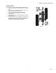
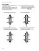

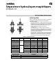
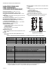
Table Of Contents

MAGNETIC HYDRAULIC SEPARATORS
33-00541EF—01 4
OPERATION
The HydroSEP hydraulic separator enables to decouple the
primary circulator flow from the secondary. When the flow
running through a primary or secondary circuit exceeds the
one circulating in the other, the separator bypasses part of
the flow. This results in a production circuit featuring a
constant flow and a distribution circuit with a variable flow.
Fig. 3.
The flow enters the separator and slows down to separate
the solid debris from the fluid. The solid impurities are
separated when they collide with the metal mesh (A) and
ferrous particles are retained by the attraction force
generated by the magnet (B).
We recommend to periodically open the drain tap (C) on the
lower end of the separator to discharge possible debris
collected on the bottom of the separator.
Fig. 4.
INSTALLATION
The HydroSEP hydraulic separator can be installed in
heating/cooling systems where there is a main circulator and
two or more secondary circulators.
The HydroSEP hydraulic separator can be installed on hori-
zontal pipes. The product cannot be installed in horizontal
position and upside down (air vent valve downwards).
When removing the magnet, ensure a space of at least
6 inches is left in the frontal part of the hydraulic separator.
For periodic cleaning, see the section on maintenance.
Fig. 5.
WARNING
The symbol on the magnet cap indicates the presence
of magnetic fields, which can cause damage to
electronic devices (including pacemakers) that are
placed in close proximity.
Union models
1. Install the air vent valve on the upper spacer of the
separator body.
2. Install the drain tap with 3/4 inch GHT connection and
cap on the lower spacer of the separator body.
3. Install the self-sealing plug on the top front connection
of the separator body.
4. Install the self-sealing magnet kit on the lower front
connection of the separator body.
5. Install the fitting adapters on the side spacer of the
separator body.
6. Install the insulation shell with adhesive seal on the
separator body, making sure to leave the aluminum
tabs on the outside.
7. Fold the adhesive aluminum tabs to seal the insulation.
8. Once all components are installed, the separator must
be assembled in vertical position, with the air vent
valve placed on the upper spacer, and connected.
Fig. 6.
Q
I
> Q
II
Q
I
Q
II
Q
I
Q
II
Q
I
< Q
II
A
C
B