RTF00 04N1AL59 9UA
RTF004N1AL59UA Table of Contents 4 Mechanical characteristic(JN5169) .................. 8 5 Pin Diagram and Description(JN5169) ............. 9 Glossary of Terms ................................................... 2 1 2 3 RTF004N1AL59UA .......................................... 4 Antennas ......................................................... 13 6 Mechanical characteristic ............................... 14 1.1.1 Description ................................
RTF004N1AL59UA @2019Resideotechnologylnc..
RTF004N1AL59UA 1 RTF004N1AL59UA 1.1.1 Description RTF004N1AL59UA module is a highly integrated a 2.4 GHz(2405MHz~2480MHz) wireless module, two-way micro-controller based radio transceiver which integrates into the security family of sensors. It has rich peripherals and high link budget to communication. RTF004N1AL59UA complies with IEEE802.15.4 and integrates 3 wires Co-exist, 1x IIC,2x ADC, 4wires USART, 2wires UART, making it a complete RF6 solution. 1.1.2 Module 1.1.
RTF004N1AL59UA Smart Grid and Automatic Meter Reading – Water, Gas, and Electricity Meters – Heat Cost Allocators – Gateways Wireless Sensor Networks – Long-Range Sensor Applications Industrial – Asset Tracking and Management – Factory Automation 1.1.
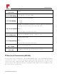
RT TF004N1AL59 9UA 2 Mod dule Fun nction B Block(JN5169) @2019Resid deotechnologyylnc..
RTF004N1AL59UA 2.1.1 VCC 2.1.2 JTAG debug 2~3.6V Tied together Jtag and USART1 Need have Uart for FCT/Debug 2.1.3 Uart debug •TXD •RXD AP mode: If need work with WiFi or other 2.4Ghz wireless module, need use 3 co-ext singles to align time slot 2.1.4 Co-ext signals Notes They are share with SPI flash pins 2.1.5 FEM VCC1 Need reserve FEM VCC1 debug, keep it float For FW update usage 2.1.6 Programming Notes They are share with SPI flash pins 2.1.7 Reset 2.1.
RTF004N1AL59UA 3.1.1 Basic conditions Parameter Input Voltage (Vbat) Min. Typ. Max. Units 0 Operating -40 Temperature — 3.6 V — 85 ºC 3.1.2 DC Characteristic Parameter Min. Typ. Max. Units I/O current sink/source capability — 10 — mA Supply voltage 2 — 3.6 V 3.1.3 ADC Characteristic Parameter Description Min. Typ. Max. Units Resolution 4 200kHz Clock — — 12 Bits Mechanical characteristic(JN5169) Module Specification Dimensions @2019Resideotechnologylnc..
RT TF004N1AL59 9UA 5 Pin Diagram m and Descript D tion(JN5169) RTF004N1AL59UA RTF004N1AL59UA Pin Nu umber Pin Name N JN5169 Descriiption Number 1 GND Ground 2 ANT1 RF signal antenna 1 3 GND Ground 4 GND Ground 5 debug_uartt_TX debug port @2019Resid deotechnology ylnc..
RTF004N1AL59UA 6 debug_uart_RX debug port 7 FEM VCC1 Keep float 8 GND Ground 9 coext1 10 coext2 11 coext3 co-exist pin with WiFi&BLE co-exist pin with WiFi&BLE co-exist pin with WiFi&BLE 40 DIO15 23 DIO18 24 DIO19 20 DIO0 22 DIO1 27 DIO5 26 DIO4 28 DIO6 29 DIO7 24 DIO19 when low power up, 12 Programming enter into UART prgram mode 13 GND Ground 14 NC No connect 15 NC No connect 16 GND Ground 17 NC No connect 18 NC No connect 19 UART1_RTS 20 UART1_
RTF004N1AL59UA 26 GND Ground 27 GND Ground 28 VDD Power input 29 VDD Power input 30 GND Ground 31 GND Ground 32 ADC2 ADC input 11 ADC2 33 ADC1 ADC input 15 ADC1 34 GND Ground 35 nRST reset input 3 nRST 36 I2C_SDA Serial DatA 2 DIO17 37 I2C_SCL Serial CLock 1 DIO16 38 GND Ground 39 nINT1 31 DIO8 40 nINT2 34 DIO11 41 NC No connect 42 GND Ground 43 SPIFLASH_CLK 20 DIO0 44 SPIFLASH_MISO 22 DIO1 45 GND Ground 46 GND Ground 23 DIO18 4
RTF004N1AL59UA 49 GND Ground 50 GND Ground 51 GND Ground 52 GND Ground 53 GND Ground 54 GND Ground 55 GND Ground 56 GND Ground 57 ANT2 RF signal antenna 2 58 GND Ground 59 GND Ground @2019Resideotechnologylnc..
RTF004N1AL59UA Antennas Current design use external antenna, SATIMO company antenna PN is SD2450, dipole type antenna, the nominal dipole impedance is 50ohm with return loss value better than -15dB at the labeled center frequency and better than -10dB return loss in a bandwidth of 10%. For the more information, please see antenna test report.
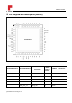
RTF004N1AL59UA 6 Mechanical characteristic Table 3-1shows the weight anddimensions.Figure 3-2 shows thephysical dimensions for the RTF004N1AL59UAmodule. Table3-2: Mechanical characteristic Specification Dimensions Description 12x15x2.5 mm Figure 3-1: RTF004N1AL59UAModule Dimensions @2019Resideotechnologylnc..
RTF004N1AL59UA @2019Resideotechnologylnc..
RTF004N1AL59UA FCC Certification Requirements. According to the definition of mobile and fixed device is described in Part 2.1091(b), this device is a mobile device. And the following conditions must be met: 1. This Modular Approval is limited to OEM installation for mobile and fixed applications only.
RTF004N1AL59UA For this device, OEM integrators must be provided with labeling instructions of finished products. Please refer to KDB784748 D01 v07, section 8. Page 6/7 last two paragraphs: A certified modular has the option to use a permanently affixed label, or an electronic label. For a permanently affixed label, the module must be labeled with an FCC ID - Section 2.926 (see 2.2 Certification (labeling requirements) above).
RTF004N1AL59UA @2019Resideotechnologylnc..
RTF004N1AL59UA 7 Revision History Revision A (September 2019) This is the initial release of this document @2019Resideotechnologylnc..
FCC Certification Requirements. According to the definition of mobile and fixed device is described in Part 2.1091(b), this device is a mobile device. And the following conditions must be met: 1. This Modular Approval is limited to OEM installation for mobile and fixed applications only.
If the device is used for other equipment that separate approval is required for all other operating configurations, including portable configurations with respect to 2.1093 and different antenna configurations. For this device, OEM integrators must be provided with labeling instructions of finished products. Please refer to KDB784748 D01 v07, section 8. Page 6/7 last two paragraphs: A certified modular has the option to use a permanently affixed label, or an electronic label.