SERVICE MANUAL 300T Ver.1.0 f f ff f Phase ELECTRONIC AIR PURIFIER Model No. RespirAide 300T n tio d uc re od ito Pr on m S t e a fe st ty ed RISK OF ELECTRIC SHOCK! This servicing manual is for use by qualified personnel only. To reduce the risk of electric shock, do not perform any servicing other than that contained in the operating manual unless you are qualified to do so.
PART I GENERAL DESCRIPTION ON AIR CLEANING 1. IN DOOR AIR QUALITY If you could see the air you breathe under a microscope, you might be in for a surprise. The air quality is much more terrible than you may think. In fact, floating in indoor air is a "soup" of particles too small to be seen by your naked eye. But it is large enough to cause problems. Visible dust makes up only 1% of all the particles in the air. The vast majority of particles are microscopic.
PART I GENERAL DESCRIPTION ON AIR CLEANING A wide variety of molds also can produce mycotoxins at various times during their lifecycles. Building occupants can experience potentially serious health problems if they are exposed to high levels of these compounds, but this is rare in most indoor environments. Although becoming a lesser issue in public buildings, ETS is still found in many homes, hotels, casinos, and in some restaurants and bars.
PART I GENERAL DESCRIPTION ON AIR CLEANING 2. AIR CLEANING TECHNOLOGY When you are trying to repair the air purifiers, make sure you understand the technologies used by the air purifier and the potential issues that may be inherent in that technology which could effect the efficiency of the air purifier and your health. Most of air purifiers may use multiple technologies in their design.
PART I GENERAL DESCRIPTION ON AIR CLEANING Electret media filter-synthetic (Hybrid Filters) Electret media filter is a hybrid of a mechanical filter and electrostatic filter or an ion generator in an integrated single filter. The media filter made from synthetic fibers is inherently negatively charged in the manufacturing process and retains a charge which attracts airborne particles that are trapped and retained within the fibers in the conventional methods of impingement.
PART I GENERAL DESCRIPTION ON AIR CLEANING Activated Carbon Filter The activated carbon filter can remove gas and odor. This is the physical process of binding gas molecules to a large surface or pores of an adsorbent medium.
PART I GENERAL DESCRIPTION ON AIR CLEANING Photo catalyst A photo catalyst is a chemical compound that becomes highly reactive when exposed to various wavelengths of UV light. Photo catalytic oxidation is achieved when UV light rays is combined with a TiO2 coated filter. TiO2 refers to Titanium Oxide. This process creates hydroxyl radicals and super-oxide ions, which are highly reactive electrons.
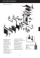
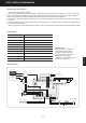
PART II PRODUCT INFORMATION 211301 Exploded view and part names 211201 211302 211303 211503 211120 211121 211202 211504 211203 211117 211118 211804 101201 211114 211101 101318 211801 101503 101311 211102 101319 101316 ENGLISH 211107 211506 101315 211906 211105 211509 101313 211304 211905 101306 211508 101301 211903 (Complete) 211201 Plastic top cover 211301 Display circuit board 211302 Odor sensor 211303 Remote receiver 211503 Outlet screen 211121 Screen metal frame 211120 Fan mot
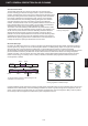
PART II PRODUCT INFORMATION The sixe stages of air cleaning 1. The Pre-filter traps large dust particles. 2. The two-stage electrostatic precipitator (Electronic cell) captures airborne particles, as small as 0.01 microns. In the ionizing section of the electronic cell, billions of microscopic particles become electrically charged as they pass through the powerful electric field. The collector plates immediately attract and collect these charged dust and dirt particles. 3.
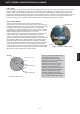
PART III IMPORTANT PARTS - PRE FILTER PRE FILTER The pre filter is an important part of the unit. Large particles (lint, hair) are caught by the pre filter to protect the electronic cell. Cleaning the Pre filter regularly To ensure optimum performance from the air purifier, the pre filter and cell must be cleaned regularly-every one to three months. Washing frequency will vary depending on the number of family members, pets, activities (such as cooking or woodworking) and smoking habits.
PART III IMPORTANT PARTS - ELECTRONIC CELL ELECTRONIC CELL The electronic cell ( electrostatic precipitator) is one of most important parts of the unit. The unit employs a two-stage electronic cell for particulates collection. It has a stage of ionizer wires and a stage of collector plates. The ionizer wires are maintained at several thousand volts, which produce a corona that releases electrons into the air stream.
PART III IMPORTANT PARTS - ELECTRONIC CELL Exploded view of electronic cell 211517 (x12) 211518 (x5) 101507 211515 (x35) 211516 (x36) 211510 211512 211519 (x5) 101513 (x345) 211511 101514 (x10) 211514 211907 211513 101802 (x4) Part Number Description Qty Interchangeable 211510 Cell 1st stage plate 1 200T 211511 Cell side plate 2 200T 211512 Join side plate 1 200T 211513 Ionizing wire latch 2 200T 211514 Ionizing wire hook 2 200T 211515 2nd stage ground plate 35 200T 211
PART III IMPORTANT PARTS - ELECTRONIC CELL Specifications of electronic cell Part model 200-5p Dimmensions 39.4cmx42cmx11cm Weight 3.8kg Collecting surface area 1.95m2 Particl removal efficiency 95%-98%< 0.3microns~0.5microns Power consumption 4.77W@7.8KV dc WARNING 1. DO NOT clean the cell with alcohol, gasoline, paint thinner or other flammable substances. It may cause fire! 2. DO NOT reinstall the cell until it is completely dry.
PART III IMPORTANT PARTS - ACTIVATED CARBON FILTER ACTIVATED CARBON FILTER The activated carbon filter is also one of the important parts of the unit. The activated carbon filter of the unit is located behind the electronic cell. Activated carbon, the universal adsorbent, has a capacity for virtually all vapor contaminants and will adsorb and retain a wide variety of chemicals at the same time. The adsorb diffuses thru the surface film to the macropore structure.
PART III IMPORTANT PARTS - UV LAMP AND PHOTO CATALYST UV LAMP After removing the activated carbon filter, you will see a UV lamp behind the UV light blocker and photo catalyst behind them. The unit utilizes 6 watt UVC lamps in the 254 nm range and photo catalyst. The UV lamp is effective in destroying the nucleic acids in these organisms so that their DNA is disrupted by the UV radiation. When the photo catalyst (TiO2) captures UV light, it forms activated oxygen from oxygen in the air.
PART III IMPORTANT PARTS - NEGATIVE ION GENERATOR NEGATIVE ION GENERATOR The negative ion generator is secured to the upper portion of the left fan housing by a screw and the brush terminal is on the air outlet. The negative ion has 3 wires, the black and red wire is input wires connecting to the main circuit board and the white wire with brush terminal is output wire. Negative ion generator holder on the left fan housing . Negative ion generator wire plug under the fan motor top plate.
PART III IMPORTANT PARTS - INTERLOCK SWITCH INTERLOCK SWITCH The interlock switch is provided with a lever which can be actuated by the actuator on the front panel. The interlock switch opens all supply conductors simultaneously when opening the front panel for servicing. When the front panel is closed the actuator pushes down the interlock switch levers and the unit will operate.
PART III IMPORTANT PARTS - MAIN CIRCUIT BOARD MAIN CIRCUIT BOARD The main circuit board is the most important parts of the unit. Pressing any buttons on the control panel will control the main circuit board through the display circuit board wire for the unit to carry out the desired functions. There will no display lights or incorrect display on the display panel if the display circuit board wire connections are loosened, the main circuit board or display circuit boards are broken.
PART III IMPORTANT PARTS - MAIN CIRCUIT BOARD Replace main circuit board It is important to remember that the main circuit board will be rarely broken down. For example, when the check light is flashing you need to check the cell or power supply do not replace the main circuit board if you do not have evidence that the main circuit board is really broken. 1. Unplug the red check wire connection. 2. Unplug the odor sensor wire connection. 3. Remove the negative ion generator wire connection. 4.
PART III IMPORTANT PARTS - MAIN CIRCUIT BOARD Disassemble main circuit board The ground portion of main circuit board. 2. Remove the main circuit board. 1. Remove 4 screws on the circuit board. Install main circuit board When install the circuit board, do the reversion operation. Make sure all the connection are correctly connected. ENGLISH Replace the main circuit board transformer 1. Unplug the transformer wir plug from the circuit board. 2. Remove 2 screws on the main circuit board transformer.
PART III IMPORTANT PARTS - POWER SUPPLY AND TRANSFORMER POWER SUPPLY The power supply is one of the most important parts of the unit. The power supply provides high voltages to the cell through the power contact plates. The red wire twin check wire connect the main circuit board.
PART III IMPORTANT PARTS - POWER SUPPLY AND TRANSFORMER Check and working light on the power supply 1. The green working light illuminate. The unit is working correctly. 2. When the green light is on but the red check light flashes and the CHECK indicator light on the control panel comes on. You need to check if you put the cell in the unit or try to put the cell correctly. 4. The 2 lights do not light up, check the power supply, power supply transformer and main circuit board. 5.
PART III IMPORTANT PARTS - POWER SUPPLY AND TRANSFORMER Adjust the power supply high voltage output Electronic cell generates a small amount of ozone, about 0.005 to 0.010 parts per million (ppm). The average person can detect the odor of ozone in concentrations as low as 0.003 to 0.010 ppm. The U.S. Food and Drug Administration and Health and Welfare Canada recommend that indoor ozone concentration should not exceed 0.050 ppm.
PART III IMPORTANT PARTS - POWER SUPPLY AND TRANSFORMER Replace power supply 2. Put a screw on the circuit 3. Put the red check wire under the circuit board before setting a screw on the circuit board but do not tight up. 4. Screw the power supply ground wire connection. Finally, tight up all the screws on the circuit board. 5. Plug the red twin check wire on the power supply circuit board. 6. Plug the transformer connection correctly. ENGLISH 1. Prepare a new power supply and 4 screws.
PART III IMPORTANT PARTS - POWER SUPPLY AND TRANSFORMER Adjust the power supply high voltage output Electronic cell generates a small amount of ozone, about 0.005 to 0.010 parts per million (ppm). The average person can detect the odor of ozone in concentrations as low as 0.003 to 0.010 ppm. The U.S. Food and Drug Administration and Health and Welfare Canada recommend that indoor ozone concentration should not exceed 0.050 ppm.
PART III IMPORTANT PARTS - POWER SUPPLY AND TRANSFORMER Replace the power supply transformer When you disassemble the power supply you will follow the below steps and simply do the reverse operation to install the transformer. Make sure all the wires are connected correctly. 2. Unscrew a black screw on the cable casing with cross screwdriver. 4. Remove two screws on the green socket with slotted screwdriver. 5.
PART III IMPORTANT PARTS - FAN MOTOR SYSTEM FAN MOTOR SYSTEM After removing the plastic top cover, you will find the fan motor system. The fan motor system is composed of two fan housings and radial type fan blades, single phase AC motor and capacitor. Replace the fan motor When replacing the fan motor system you need to follow the below steps and do the reverse operation to install the fan motor system. 2. Remove the fan motor front panel. 3. Unscrew 3 screws under the plastic top cover. 4.
PART III IMPORTANT PARTS - FAN MOTOR SYSTEM 11. Unplug the fan motor cable connection. 12. Lift out the fan motor complete. ENGLISH Helpful hints You need to remove 6 screws on the fan motor top plate to take off the fan motor complete (See right picture). A helpful guide for replacing the motor 1. Open a nut on the motor shaft with a nut screwdriver, counter clock wise with the right side nut. 3. Open another nut on the motor shaft with a socket wrench, clock wise with the left side nut. 4.
PART III IMPORTANT PARTS - FAN MOTOR SYSTEM Helpful hints To prevent the trembling use spring rubber washer and flat washer when installing the motor. Motor type Spring and flat washer Rubber washer Capacitor run AC motor Power requirement 120V, 60Hz Rated Power 20W, 0.
PART III IMPORTANT PARTS - DISPLAY CIRCUIT BOARD DISPLAY CIRCUIT BOARD The display circuit board is one of the most important parts of the unit. It is located inside the plastic top cover. The circuit board is connected to the main circuit board by display circuit board wire. If the display circuit board wire connections are loosened, or circuit boards are broken there will no display lights or incorrect display indicator lights on the display panel.
PART III IMPORTANT PARTS - DISPLAY CIRCUIT BOARD 6. Unplug the odor sensor. 7. Unplug the remote receiver wire from the display circuit board. 8. Unscrew the ground wire of screw on the display circuit board. Add a spring washer 9. Unscrew a screw on the display circuit board. 10. Lift out the display circuit board from the plastic top cover. Negative ground wire ENGLISH Take off and install the front panel 1.
PART IV TROUBLESHOOTING - CHECK LIGHT FLASHING CHECK LIGHT FLASHING When the unit is turned on, the CHECK indicator light flashes and you may hear warning beep sound. When you open the unit bottom plate you will see the twin red check wires between power supply and main circuit board. The main circuit board is always detecting the voltage on this check wires when the unit is turned on.
PART IV TROUBLESHOOTING - CHECK LIGHT FLASHING Step 1 Check electronic cell Check the electronic cell 1. If the cell is put in opposite way or missing to put cell in the unit? It will cause the CHECK indicator light on the control panel flashing. 2. Lift the cell in front of a bright light and look through, visually inspect if there are broken or bent ionizer wires or if the collector plates are bent or deformed. 3. If the cell is wet after washing or with other reasons? Please dry the cell thoroughly.
PART IV TROUBLESHOOTING - CHECK LIGHT FLASHING Step 3 Check power supply transformer Check power supply transformer 1. Set the ohmmeter at 200V ac. 2. Check power voltage on the power supply cord plug. It should read somewhere close to 18V ac. Helpful hints The green and red light on the power supply do not illuminate. 3. Check voltage on power supply connection of the main circuit board. It should read somewhere close to ac.
PART IV TROUBLESHOOTING - NO POWER NO POWER When the unit is plugged in, there are no display indicator lights on the control panel and no any melody. The buttons and remote control do not start the unit. Repair tips: 1. Check power cord plug and outlet 2. Check front panel 3. Check interlock switch 4. Check fuse 5. Check main circuit board transformer 6. Check main circuit board WARNING Some of these steps expose dangerous high voltage. Only qualified service technician should attempt this procedure.
PART IV TROUBLESHOOTING - NO POWER Step 1 Check power cord plug and outlet Check power cord plug and outlet 1. Sometimes, the unit does not operate because of the electrical outlet failure. Check if other electrical appliances using the same electrical outlet are working. 2. Make sure the power plug is inserted into the wall outlet correctly, or try to check if the power cord socket on the unit is installed correctly. 1. Make sure the power plug is tightly inserted into the outlet. 2.
PART IV TROUBLESHOOTING - NO POWER Replace interlock switch If the unit still has no power after adjusting the interlock switch height you need to replace the interlock switch. Remember the interlock switch is not easily broken. To replace the interlock switch see IMPORTANT PARTINTERLOCK SWITCH on page 17. Step 4 Check fuse Check the fuse ENGLISH Now that the interlock switch is no problem, you should go ahead to check the fuse.
PART IV TROUBLESHOOTING - NO POWER Why does the fuse keep damaging? After replacing the blown fuse with a new one, try to operate the unit but new fuse is still blown out with unknown reasons. To fix this problem, you have to spend time to check all the electrical wires in the unit. At first, check if the electrical wire casing is damaged. The damaged wires will cause a short circuit between them or the damaged Live line may touch the unit metal casing to create a short circuit.
PART IV TROUBLESHOOTING - NO POWER Step 5 Check main circuit board transformer Check main circuit board transformer If the fuse is OK, you will go ahead to check the main circuit board transformer. 1. Set the ohmmeter on AC 200V. 2. Check the red wire voltage, it should read about 110~120V ac. 3. Check the blue wire voltage, it should read about 12V. If it reads 00.0, the transformer has problem. You need to replace the main circuit board transformer.
PART IV TROUBLESHOOTING - NO FAN NO FAN When the unit is turned on, the fan doesn't work properly. When the speed is switched, the fan has incorrect speed rates. Repair tips: 1. Check fan motor wire connection 2. Check fan motor capacitor 3. Check main circuit board 4. Check fan motor. WARNING Some of these steps expose dangerous high voltage. Only qualified service technician should attempt this procedure.
PART IV TROUBLESHOOTING - NO FAN Step 1 No fan with incorrect display lights No fan with incorrect display lights When the unit is powered on, the display lights show incorrect and some buttons do not work properly. Most of time, this problem is due to display circuit board wire loose. 1. Open the bottom plate, fasten the display circuit board wire connection. 2. Open the top plastic cover, fasten the connection of the display circuit board. Fasten the display circuit board wire on the main circuit board.
PART IV TROUBLESHOOTING - NO FAN Check main circuit board 1. Set the ohmmeter at the range of 200V ac. 2. With the ohmmeter, check three speeds output voltages. Make sure the unit is plugged in. A. Set at Low speed, place the terminals on yellow (com) and black (L) wires, it should read somewhere close to 120V ac. If not, the main circuit board has problem. B. Set at Medium speed, the yellow and blue (M) wires should read somewhat close to 120V ac. If not, the main circuit board has problem. C.
PART IV TROUBLESHOOTING - NO FAN Replace the fan motor If the motor still does not run correctly after replacing the motor capacitor, you will go ahead to replace the fan motor. To replace the fan motor see IMPORTANT PART-FAN MOTOR SYSTEM on page 27. Step 3 Incorrect air flow Incorrect air flow When the 3 speed of the fan motor is not correct, you will need to check the main circuit board, fan motor and the power source. Check the main circuit board 1. Open the bottom plate. 2.
PART IV TROUBLESHOOTING - NO FAN Check the fan motor If the fan motor cable connection is correctly all the connections are correctly connected, you need to replace the fan motor. To replace the fan motor see IMPORTANT PART-MAIN FAN MOTOR SYSTEM on page 27. Check the power source ENGLISH Sometimes, the problem is because of the incorrect power source. You can check it with ohmmeter, it should be close to 120V ac. If not, do not operate the unit.
PART IV TROUBLESHOOTING - UNIT RESET Step 1 Check remote control When the CARBON FILTER (FILTER LIFE) or UV LAMP indicator light flashes you need to replace them. After replacing the activated carbon filter or UV lamp, you need to reset the timer. When the CELL CLEANING indicator light flashes, you also need to reset after cleaning the cell. 1. When the CARBON FILTER indicator light flashes, you need to change the activated carbon filter and press the RESET 1 button on the remote control 5 times to reset.
PART IV TROUBLESHOOTING - UNIT RESET New remote control (for B, C, D serial number units) From the units starting with R300xxxxB/C/D, there is just one RESET button on the right upper of the remote control. You can press 3-5 times to reset CARBON FILTER, UV LAMP or the CLEAN CELL indicator light flashing. POWER TIMER UV LAMP NEG. ION AUTO NIGHT ENGLISH 1.
PART IV TROUBLESHOOTING - UNIT RESET POWER reset button (from C model number units) When you cannot reset the unit with remote control you can try to hold (Do not press) the POWER button 3 seconds to reset CARBON FILTER, UV LAMP or CLEAN CELL indicator light. Press the button once to reset the FILTER LIFE and hold 5 seconds to reset UV LAMP. Hold the POWER button 3 seconds to reset CARBON FILTER, UV LAMP or CLEAN CELL indicator light. Step 3 Main circuit board reset button 1. Open the bottom plate. 2.
PART IV TROUBLESHOOTING - THE BUTTONS DO NOT WORK THE BUTTONS DO NOT WORK When the unit is plugged in the melody comes on but the buttons do not work, or the unit turns on but the buttons freeze and a click sound is heard. It sounds like sparking. Most of time, this problem occurs because of sparking. Any sparking can interfere with the display circuit board wire to cause incorrect display lights or freeze the buttons. Repair tips: 1. Sparking from the cell 2. Power contact board sparking 1.
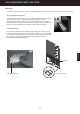
When the unit is turned on, the UV light does not light up. PART IV TROUBLESHOOTING - NO UV LIGHT NO UV LIGHT When the unit is turned on, the UV light does not light up. Repair tips: 1. Check UV lamp 2. Check UV lamp power cord and ballast 3. Check main circuit board WARNING Some of these steps expose dangerous high voltage. Only qualified service technician should attempt this procedure. TROUBLESHOOTING CHART Step 1 Check UV lamp Visually check the UV bulb. If it is broken or damaged replace it.
PART IV TROUBLESHOOTING - NO UV LIGHT Step 1 Check UV lamp Note: The UV lamp ballast is located inside the UV lamp holder. 1. Stop the operation and unplug the unit power cord from the electrical outlet. 2. Take off the front panel. 3. Unscrew the swing nut and remove the UV light blocker. 4. Unplug the UV lamp plastic plug and remove the stickers on the end of the UV lamp. 5. Visually check the UV lamp. If the UV lamps are broken or damaged, replace it. 6.
PART IV TROUBLESHOOTING - NO UV LIGHT Replace the UV lamp ballast Lift the UV lamp holder with flat screwdriver and take it out. Step 3 When you find there is no voltage on the UV lamp power cord, you will go ahead to open the bottom plate and check the main circuit board. 1. Unplug the power cord from the unit. 2. Put the unit on the table. 3. Remove the bottom plate by unscrewing 4 screws with cross screwdriver. 4. Set the ohmmeter at the Volt ac range of 200V ac.
PART IV TROUBLESHOOTING -ELECTRICAL SHOCK ELECTRICAL SHOCK Electrical shock occurs when touching the front panel. Repair tips: 1. Check Pre filter and cell ground clips 2. Check cell ground contact plate 1. Check Pre filter and cell ground clips Adjust Pre filter ground clip so that it can contact the Pre filter and cell clips correctly. 2. Check cell ground contact plate A. Open the bottom plate. B.
PART V APPENDIX - CHANGES OF THE UNIT Serial number Features and changes A 1h 2 RESET buttons 1. Press the RESET 1 button 5 times to reset the timer for FILTER LIFE. R3000001A ~ R3000350A 2. Press the RESET 2 button 5 times to reset UV LAMP. CHECK FILTER LIFE 2h 3h L M TIMER SPEED UV LAMP NEG. ION H AUTO POWER ON TIMER Button Press the TIMER button to select the time for operation.
RespirAide Tech Inc. 13-100 Hanlan Road Woodbridge, Ontario Canada L4L 4V8 Tel: 1-866-874-2532 Fax: 1-905-850-5553 www.respiraide.