with SmartCard User Manual
© 2009 Respironics, Inc. and its affiliates. All rights reserved.
TABLE OF CONTENTS Chapter : Package Contents ................................................................................................................ Chapter : Warnings and Cautions ...................................................................................................... . Warnings.................................................................................................................................... . Cautions ........................................................
Chapter : Alarms ................................................................................................................................. . Introduction to Alarms ........................................................................................................ . What to Do When an Alarm Occurs.................................................................................... . Alarm Tables .........................................................................................
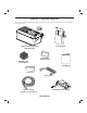
1 CHAPTER 1: PACKAGE CONTENTS Your device should include the following items. If any of these items are missing, contact your health care professional. Carrying Case BiPAP autoSV Advanced with SmartCard Reusable Gray Foam Filters Disposable Ultra-fine Filter User Manual Filter Cap Power Cord Flexible Tubing 1.83 m (6 ft.) x 22 mm i.d.
2 CHAPTER 2: WARNINGS AND CAUTIONS WARNING: Indicates the possibility of injury to the user or operator. CAUTION: Indicates the possibility of damage to the device. NOTE: Places emphasis on an operating characteristic. Caution: U.S. federal law restricts this device to sale by or on the order of a physician. 2.1 WARNINGS • • • • • • • • • • This manual serves as a reference. The instructions in this manual are not intended to supersede the instructions of your health care professional.
3 • • • • • • • • • • • • • Explanation of the Warning: The device is intended to be used with special masks or connectors that have exhalation ports to allow continuous flow of air out of the mask. When the device is turned on and functioning properly, new air from the device flushes the exhaled air out through the mask exhalation port. However, when the device is not operating, enough fresh air will not be provided through the mask, and exhaled air may be rebreathed.
4 2.2 CAUTIONS • • • • • • NOTE: The device may only be operated at temperatures between 41° F (5° C) and 95° F (35° C). A properly installed, undamaged reusable foam inlet filter is required for proper operation. Do not immerse the device or allow any liquid to enter the enclosure or the inlet filter. Do not place the device in or on any container that can collect or hold water. Condensation may damage the device. Always allow the device to reach room temperature before use.
5 CHAPTER 3: INTRODUCTION TO THE DEVICE 3.1 DEFINITIONS The following terms appear throughout this manual: Apnea A condition marked by the cessation of spontaneous breathing. BPM Breaths Per Minute CPAP Continuous Positive Airway Pressure EPAP Expiratory Positive Airway Pressure Exhaled Tidal Volume (VTE ) The exhaled volume of each breath High Priority Alarm An alarm signal indicating a condition that requires immediate attention.
6 3.2 WHAT IS BI-LEVEL VENTILATION? Bi-level ventilation with the device helps you to breathe by supplying two levels of air pressure. The device provides a higher pressure—known as IPAP (Inspiratory Positive Airway Pressure)—when you inhale, and a lower pressure—known as EPAP (Expiratory Positive Airway Pressure)—when you exhale. The higher pressure makes it easier for you to inhale, and the lower pressure makes it easier for you to exhale.
7 A breathing circuit, shown in Figure 3–3, consists of: • Circuit tubing to deliver air from the device to your interface (e.g.
8 3.4 SYMBOLS The symbols shown below are used on the device, the AC power supply, and throughout this manual. Symbol Meaning Attention, consult accompanying documents DC Power Pressure On/Off Type BF Applied Part Class II (Double Insulated) European CE Declaration of Conformity Canadian/US Certification Electrostatic Discharge IPX1 Drip Proof Equipment UL Recognized for Canada and the United States TUV Safety Standard Compliance No User Serviceable Parts 3.
9 CHAPTER 4: DEVICE CONTROLS AND DISPLAY FEATURES Figure 4–1 shows the location of the device’s alarm power indicators, control panel, Pressure On/Off button, and the breathing circuit connection. Alarm and Power Indicators Control Panel Breathing Circuit Connection Pressure On/Off Button Figure 4–1 Device Front and Top 4.1 PRESSURE ON/OFF BUTTON The device’s Pressure On/Off airflow.
10 4.2 CONTROL PANEL The control panel contains the following control buttons and indicators. 4.2.1 CONTROL BUTTONS The control buttons on the control panel are shown in Figure 4–3. Display Screen Scroll Button Pressure On/Off Button Alarm Reset Button RESET HEAT RAMP Heated Humidifier Button SILENCE User Buttons Ramp Button Alarm Silence Button Figure 4–3 Control Panel HEAT When the optional REMstar Heated Humidifier has been prescribed, this button controls the humidifier’s output.
11 4.2.2 ALARM AND POWER INDICATORS Figure 4–4 shows the device’s alarm and power indicators. AC Power Indicator (Green) High Priority Alarm LED (Red) AC Alarms Power DC DC Power Indicator (Green) Low/Medium Priority Alarm LED (Yellow) Figure 4–4 Alarm and Power Indicators AC Power Indicator The green AC Power LED lights up when the device is connected to AC Power. DC Power Indicator The green DC Power LED lights up when the device is connected to DC power.
12 The information shown on the display screen is defined as follows: ALARM Indicates that the device requires user attention as indicated on the screen. APNEA Indicates that an apnea alarm has occurred. BPM CARD cm H2O EPAP Max EPAP Min Indicates that a breath rate setting is being displayed. This symbol flashes when the device is providing timed backup breaths. Indicates that a SmartCard is inserted and detected. Indicates that the alphanumeric digits are displaying a pressure value.
13 4.2.4 BREATHING CIRCUIT CONNECTION Figure 4–6 shows where the circuit tubing connects to the device. Patient Interface Exhalation Port Circuit Tubing Bacteria Filter (Optional) Breathing Circuit Connection Figure 4–6 Typical Breathing Circuit Connection 4.2.5 REAR PANEL Figure 4–7 shows the device’s rear panel.
14 CHAPTER 5: SETTING UP THE DEVICE 5.1 INSTALLING THE AIR FILTERS The device uses one or two removable filters at the air inlet. The disposable white ultra-fine filter is optional. You must install the gray foam filter before operating the device. The foam filter is washable and reusable. CAUTION: A properly installed, undamaged foam filter is required for proper operation.
15 5.3 CONNECTING THE BREATHING CIRCUIT To connect your breathing circuit to the device, complete the following steps: 1. Connect one end of the circuit tubing to the outlet of the bacteria filter (if using one) and connect the inlet of the bacteria filter to the large connector on the device as shown in Figure 5–2. If you are not using a bacteria filter, connect the end of the circuit tubing directly to the outlet connector on the device.
16 B. If you are using a mask with a separate exhalation device, connect the open end of the circuit tubing to the exhalation device as shown in Figure 5–4. Position the exhalation device so that the vented air is blowing away from your face. Circuit Tubing Exhalation Port Figure 5–4 Connecting a Exhalation Device Connect the mask’s connector to the exhalation device, as shown in Figure 5–5. See the mask instructions for complete setup information.
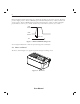
17 5.4 COMPLETE SETUP Figure 5–6 shows the completed breathing circuit setup. Patient Interface Exhalation Port Circuit Tubing Bacteria Filter (Optional) Breathing Circuit Connection Figure 5–6 Complete Breathing Circuit 5.5 PLUGGING THE DEVICE IN You can use AC or DC power to operate the device. WARNING: The DC power option is not intended as a battery backup when using AC power. WARNING: For proper use, the power supply must be placed feet down, in the upright position, as shown in Figure 5–7.
18 3. Leaving a small amount of slack in the cord, connect the cord on the other side of the power supply to one of the power inlets on the device, as shown in Figure 5–7. The power cord has a locking connector. To properly plug the cord in: a. Pull the locking mechanism back. b. Push the connector into place. c. Release the lock. Figure 5–7 Plugging in the AC Power Supply NOTE: You can plug the cord into either of the power inlets on the back of the device. 4.
19 CHAPTER 6: OPERATING THE DEVICE 6.1 STARTING THE DEVICE 1. Plug in the device to an AC or DC power source to power up the device. A confirmation alarm sounds, and the control pad buttons light up. NOTE: If the alarm does not sound or the buttons do not light up, the device requires servicing. Call your health care professional. Several screens appear initially during this step: a. The first screen that appears is the Self Test screen, shown in Figure 6–1.
20 NOTE: d. With the exception of the button, the control pad is inactive during these first three screens. Each of these screens appears for approximately 1-3 seconds. The next screen that appears is the Standby screen, shown in Figure 6–4. This indicates that the device is in the Standby state (the blower is off). PATIENT HEAT APNEA LIGHT CARD HOURS Figure 6–4 Standby Screen 2. Press the button to put the device into the Operate state (and turn on the airflow).
21 6.
22 3. You can exit this screen by pressing the Left or Right User buttons or the SILENCE button. For additional information on using a humidifier with the device, see Chapter 10. 4. To turn the humidifier ON/OFF, press the HEAT button until the device beeps twice and the text HEAT appears/disappears. 6.2.2 NAVIGATING THE USER DISPLAY SCREENS You can navigate the rest of the user display screens by pressing the Left and Right User keys.
23 6.2.2.1 CHANGING THE FLEX SETTING The Flex screen is displayed only if it is prescribed. If the Flex feature is enabled, you can adjust the Flex setting to find the setting that provides you with the most comfort. If the screen shown in Figure 6–8 does not display, you cannot adjust this setting. Change the Flex setting by completing the following: FLEX Figure 6–8 Flex Setting Screen 1. From either the Monitoring or Standby screens, press the Right User button until you reach this screen. 2.
24 6.2.2.3 CHANGING THE RAMP STARTING PRESSURE The device is equipped with an optional ramp feature. This feature will reduce the pressure and then gradually increase (ramp) the pressure to the prescription pressure setting so you can fall asleep more comfortably. The ramp feature is not prescribed for all users. If the screen shown in Figure 6–10 does not appear on your display, you cannot adjust this setting. To change the ramp starting pressure setting, complete the following steps: 1.
25 6.3 MONITORING MEASURED PARAMETERS You can view four measured parameters—leak, respiratory rate, minute ventilation, and exhaled tidal volume. To access these screens from the Monitoring or Standby screens, press the small circular Scroll button ( ) located near the RESET button. Figure 6–12 shows how to navigate the measured parameter screens.
26 2. Respiratory Rate Screen This screen, shown in Figure 6–14, shows the average rate of respiration for the previous six breaths. The display is updated at the end of each breath. RR BPM Figure 6–14 Respiratory Rate Screen 3. Minute Ventilation Screen This screen, shown in Figure 6–15, shows the estimated Exhaled Minute Ventilation (the volume of air received on a per minute basis) based on the average of the previous six breaths. MinVent LPM Figure 6–15 Minute Ventilation Screen NOTE: 4.
27 CHAPTER 7: ALARMS 7.1 INTRODUCTION TO ALARMS The device provides three alarm levels: high, medium, and low priority. High Priority These alarms require immediate response. The alarm signal consists of a red LED indicator and a sound that is either a periodic pattern consisting of a two-second beep followed by two seconds of silence or a pattern of three beeps, a pause, and then two more beeps. The display has ALARM at the top of the screen. The tables in Section 7.
28 7.2 WHAT TO DO WHEN AN ALARM OCCURS The following example applies to most alarm conditions. Follow these steps unless otherwise directed by the alarm tables that follow. 1. Look at the alarm indicators and listen to the alarm sound. Alarm LED Lights Up AC Alarms Power DC Figure 7–3 Alarm LED Lights Up Note the color of the LED and whether the LED is solid or flashing. 2. Look at the display for text.
29 7.3 ALARM TABLES The following tables summarize the high priority, medium priority, and low priority alarms. 7.3.1 HIGH PRIORITY ALARMS Alarm LED Red Flash Alarm Sound ••• •• Display Message Device Action Possible Cause ALARM and PATIENT flash Operates Breathing circuit is disconnected or has a large leak. Press the RESET button to reset the alarm. Reconnect the circuit or fix the leak. ALARM and APNEA flash Operates An apnea event occurred during therapy.
30 7.3.2 MEDIUM PRIORITY ALARMS Alarm LED Yellow Flash Alarm Sound Display Message ••• Device Action Possible Cause Operates Battery is nearly discharged. DC Power LED Flashes Your Action Press the RESET button to reset the alarm. Replace the battery. If the alarm continues, contact your health care professional. 7.3.
31 CHAPTER 8: TROUBLESHOOTING This chapter describes problems that you may experience with your device or mask and provides possible solutions. Problem Why It Happened What To Do The device does not operate when you button. press the If the power LED is off, there’s Check the outlet power and verify that no power at the outlet or the the device is plugged in. If the problem device is unplugged. If the continues, call your health care professional. power LED is on, the problem is in the device.
32 Problem Why It Happened What To Do Redness occurs when the mask cushion comes in contact with the skin. This could be due to improper mask fitting or improper mask cleaning. Be sure to rinse the mask thoroughly after cleaning to remove residue. See the mask cleaning instructions for detailed information. If the problem continues, contact your health care professional for a refitting or a different size mask. Redness occurs when the mask cushion accessory comes in contact with the skin.
33 Problem Why It Happened What To Do Runny nose. Nasal reaction to the air flow. Call your health care professional. The device’s display is erratic. The device or power supply has been dropped or mishandled, or the device or power supply is in an area with high EMI emissions. Unplug the device and the power supply. A SmartCard error occurs. The SmartCard is not inserted properly. It may be inserted upside down or backwards.
34 CHAPTER 9: CLEANING AND MAINTENANCE 9.1 CLEANING THE DEVICE Before cleaning or performing any routine maintenance, always make sure the device is not operating and disconnect the device from the power source. NOTE: The following cleaning instructions are for the device only. To clean the accessories, refer to each accessory’s instruction sheet. CAUTION: Do not immerse the device or allow any liquid to enter the enclosure, inlet filter, or any openings.
35 3. Remove the filters from the enclosure by gently pulling around the edges of the filters. The top filter is the reusable gray foam filter. The bottom filter is the optional disposable white ultra-fine filter, as shown in Figure 9–2. Reusable Gray Foam Filter Disposable Ultra-fine Filter Figure 9–2 Removing the Filters 4. Examine the filters regularly for cleanliness and integrity. 5. If needed, wash the gray foam filter in warm water with a mild detergent.
36 CHAPTER 10: ACCESSORIES 10.1 ADDING A HUMIDIFIER The REMstar Heated Humidifier, REMstar Passover Humidifier, and H2 Heated Humidifier are available from your health care professional. The humidifiers may reduce nasal dryness and irritation by adding moisture (and heat, if applicable) to the airflow. CAUTION: For safe operation, the humidifier must always be positioned below the circuit connection at the mask and the air outlet on the device. The humidifier must be level for proper operation.
37 CHAPTER 11: SPECIFICATIONS ENVIRONMENTAL Operating Storage Temperature 41° F (5° C) to 95° F (35° C) -4° F (-20° C) to 140° F (60° C) Relative Humidity 15 to 95% (non-condensing) 15 to 95% (non-condensing) Atmospheric Pressure (5600 feet to sea level) 83 to 102kPa PHYSICAL Dimensions: 9.75 in. L x 6.625 in. W x 4.4 in. H (24.8 cm L x 16.8 cm W x 11.2 cm H) Weight: 4 lbs (1.
38 PRESSURE Output: 4 to 30 cm H2O CONTROL ACCURACY Parameter Range Accuracy Max Pressure 4 to 30 cm H2O * Min EPAP 4 to 25 cm H2O * Max EPAP 4 to 25 cm H2O * Min Pressure Support 0 to 26 cm H2O * Max Pressure Support 0 to 26 cm H2O * Breath Rate 4 to 30 BPM Greater of ± 1 BPM or ± 10% of the setting (when measured over a 4 minute period) Timed Inspiration 0.5 to 3.0 seconds ± (0.
39 APPENDIX A: EMC INFORMATION GUIDANCE AND MANUFACTURER’S DECLARATION - ELECTROMAGNETIC EMISSIONS: This device is intended for use in the electromagnetic environment specified below. The user of this device should make sure it is used in such an environment. EMISSIONS TEST COMPLIANCE ELECTROMAGNETIC ENVIRONMENT - GUIDANCE RF emissions CISPR 11 Group 1 The device uses RF energy only for its internal function.
40 GUIDANCE AND MANUFACTURER’S DECLARATION - ELECTROMAGNETIC IMMUNITY: This device is intended for use in the electromagnetic environment specified below. The user of this device should make sure it is used in such an environment.
41 NOTES User Manual
42 NOTES User Manual
LIMITED WARRANTY Respironics, Inc. warrants that the BiPAP autoSV Advanced system shall be free from defects of workmanship and materials and will perform in accordance with the product specifications for a period of two (2) years from the date of sale by Respironics, Inc. to the dealer. If the product fails to perform in accordance with the product specifications, Respironics, Inc. will repair or replace – at its option – the defective material or part. Respironics, Inc.
REF 1058258 1056939 JB 11/25/2008