BiPAP® S/T User Manual
This BiPAP system is covered by one or more of the following patents: U.S. Patent Nos. 5,148,802; 5,313,937; 5,433,193; 5,632,269; 5,803,065; 6,029,664; 6,305,374 and 6,539,940; Australian Patent Nos. 638054, 661575, 698519, 723681, 734319, and 733655; Canadian Patent Nos. 2,162,981 and 2,259,795; European Patent Pub. No. 0425092B1; and Japanese Patent Nos. 2832812, 2137336, and 2926392. Other U.S. and Foreign Patents Pending. © 2008 Respironics, Inc, and its affiliates. All rights reserved.
Table of Contents Chapter 1: Package Contents............................................................................ 1 Chapter 2: Warnings and Cautions.................................................................. 2 2.1 Warnings................................................................................................. 2 2.2 Cautions.................................................................................................. 4 2.3 Intended Use..............................................
Chapter 7: Alarms............................................................................................. 32 7.1 Introduction to Alarms...................................................................... 32 7.2 What to Do When an Alarm Occurs................................................ 34 7.3 Alarm Tables. ....................................................................................... 35 7.3.1 High Priority Alarms. ............................................................... 35 7.3.
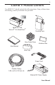
1 Chapter 1: Package Contents Your BiPAP S/T should include the following items. If any of these items are missing, contact your home care provider. BiPAP S/T with Encore® Pro SmartCard™ Carrying Case Gray Foam Filters Ultrafine Filter User Manual Filter Cap Power Cord Flexible Tubing 1.83 m (6 ft.) X 22 mm i.d.
2 Chapter 2: Warnings and Cautions WARNING: Indicates the possibility of injury to the user or operator. NOTE: Places emphasis on an operating characteristic. CAUTION: Indicates the possibility of damage to the device. 2.1 Warnings • • • • • • • This manual serves as a reference. The instructions in this manual are not intended to supersede the instructions of your health care professional. You should read and understand this entire manual before using the device.
3 • • • • • • • • • • • • • If oxygen is used with the device, the oxygen flow must be turned off when the device is not in use. Explanation of the Warning: When the device is not in operation and the oxygen flow is left on, oxygen delivered into the ventilator tubing may accumulate within the device’s enclosure. Oxygen accumulated in the ventilator enclosure will create a risk of fire. If you are using oxygen, the BiPAP S/T must be equipped with the Respironics Pressure Valve (Part number 302418).
4 • • To avoid electrical shock, unplug the device before cleaning it. Pins of connectors identified with the ESD warning symbol should not be touched. Connections should not be made to these connectors unless ESD precautionary procedures are used. Precautionary procedures include methods to prevent build-up of electrostatic discharge (e.g.
5 2.4 Contraindications The BiPAP S/T should not be used if you have severe respiratory failure without a spontaneous respiratory drive.
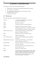
6 Chapter 3: Introduction This chapter contains the following information: • Definitions for common terms used throughout this manual • An explanation of the symbols used on the device and throughout this manual • • An overview of the device Contact information 3.1 Definitions The following terms appear throughout this manual: Apnea A condition marked by the cessation of spontaneous breathing.
7 Rise Time The time it takes for the device to change from EPAP to IPAP. You can adjust this time for your comfort. RR Respiratory Rate Spontaneous (S) A bi-level mode which responds to both your inhalation and exhalation by increasing pressure when you start to inhale and decreasing pressure when you start to exhale. There is no automatic delivery of a breath if you do not inhale.
8 The circuit, shown in Figure 3–2, consists of: • • • Circuit tubing to deliver air from the device to your interface (e.g.
9 3.3 Symbols The symbols shown below are used on the device and throughout this manual. Symbol Meaning Attention, consult accompanying documents DC Power Pressure On/Off Type BF Applied Part Class II (Double Insulated) European CE Declaration of Conformity Canadian/US Certification Electrostatic Discharge IPX1 Drip Proof Equipment UL Recognized for Canada and the United States TUV Safety Standard Compliance No User Serviceable Parts 3.
10 Chapter 4: Controls and Display Features Figure 4–1 shows the location of the device’s alarm power indicators, control panel, Pressure On/Off button, and breathing circuit connection. Alarm and Power Indicators Control Panel Breathing Circuit Connection Pressure On/Off Button Figure 4–1 Front and Top 4.1 Pressure On/Off Button The Pressure On/Off button, located on the side of the unit, starts and stops the unit’s airflow. Press the button in to turn the airflow on.
11 4.2 Control Panel The control panel contains the following control buttons and indicators. 4.2.1 Control Buttons The control buttons on the control panel are shown in Figure 4–2. Display Screen Pressure On/Off Button Alarm Reset Button RESET HEAT RAMP Heated Humidifier Button User Buttons Ramp Button SILENCE Alarm Silence Button Figure 4–2 Control Panel HEAT When the optional REMstar heated humidifier is prescribed, this button controls the humidifier’s heater plate setting.
12 4.2.2 Alarm and Power Indicators Figure 4–3 shows the device’s alarm and power indicators. AC Power Indicator (Green) High Priority Alarm LED (Red) AC Power Alarms DC DC Power Indicator (Green) Low/Medium Priority Alarm LED (Yellow) Figure 4–3 Alarm and Power Indicators AC Power Indicator This green LED lights up when the device is connected to AC Power. DC Power Indicator This green LED lights up when the device is connected to DC power.
13 4.2.3 Display Screen The display shows you the measured pressure and displays alarm messages. A backlight activates when any of the keys are pressed and remains on until there are no keystrokes for one minute. Figure 4–4 shows the display screen. Figure 4–4 Display Screen The information shown on the display screen is defined as follows: ALARM Indicates that the device requires user attention as indicated on the screen. APNEA Indicates that an apnea alarm has occurred.
14 INSP. TIME Indicates that the inspiratory time setting is being displayed. IPAP Indicates that an IPAP pressure setting is being displayed. LIGHT Indicates that the keypad LED backlight setting is being displayed or is active. PATIENT Indicates that a Patient Disconnect alarm is active. RAMP Indicates that the Ramp function is in progress. RAMP START Indicates that the Ramp Starting Pressure is being displayed. RISE TIME Indicates that a rise time setting is being displayed.
15 4.2.4 Breathing Circuit Connection Figure 4–5 shows where the circuit tubing connects to the device. Patient Interface Exhalation Port Circuit Tubing Bacteria Filter (Optional) Breathing Circuit Connection Figure 4–5 Typical Breathing Circuit Connection 4.2.5 Rear Panel Figure 4–6 shows the rear panel. Communications Connector Port Power Inlets Cord Retainer SmartCard Connector Cord Retainer Filter Cap Figure 4–6 Rear Panel NOTE: The SmartCard Connector is located on the side of the device.
16 The rear panel contains the following: Communications Connector This connector accepts the Respironics Communications cable for computer and external communications, or a remote alarm. (Use only with an IEC 60950 approved computer.) Power Inlets There are two power inlets on the rear panel, one for connecting the external AC power supply and another for connecting the external DC power adapter. Filter Cap The filter cap can be removed to inspect the inlet air filters.
17 Chapter 5: Setting up the Device This chapter provides instructions on how to: • Install the air filters • Connect the breathing circuit • • Position the unit Plug the device in using AC or DC power 5.1 Installing the Air Filters CAUTION: A properly installed, undamaged foam filter is required for proper operation. The BiPAP S/T uses a gray foam filter that is washable and reusable, and an optional white, ultra-fine filter that is disposable. One filter of each kind is supplied with the unit.
18 3. Attach the filter cap as shown in Figure 5–2. Position the cap so that the small opening on the cap is facing down. Insert the caps bottom tabs into the openings below the filter area. Snap the cap into place. Figure 5–2 Attaching the Filter Cap NOTE: The filter cap should be installed with the air inlet opening at the bottom. See Chapter 9 to clean or replace the filters. 5.2 Where to Place the BiPAP S/T Place the device on its base somewhere within easy reach of where you will use it.
19 5.3 Connecting the Breathing Circuit To connect your breathing circuit to the device, complete the following steps: 1. Connect one end of the circuit tubing to the outlet of the bacteria filter (if using one) and connect the inlet of the bacteria filter to the large connector on the device as shown in Figure 5–3. If you are not using a bacteria filter, connect the end of the circuit tubing directly to the outlet connector on the device.
20 B. If you are using a mask with a separate exhalation device, connect the open end of the circuit tubing to the exhalation device as shown in Figure 5–5. Position the exhalation device so that the vented air is blowing away from your face. Circuit Tubing Exhalation Device Figure 5–5 Connecting an Exhalation Device Connect the mask’s connector to the exhalation device, as shown in Figure 5–6. See the mask instructions for complete setup information.
21 5.4 Complete The Setup Figure 5–7 shows the completed breathing circuit setup. Patient Interface Exhalation Port Circuit Tubing Bacteria Filter (Optional) Breathing Circuit Connection Figure 5–7 Complete Breathing Circuit 5.5 Plugging It In You can use AC or DC power to operate the device. WARNING: The DC power option is not intended as a battery backup when using AC power. WARNING: For proper use, the power supply must be placed feet down, in the upright position, as shown in Figure 5–7.
22 5.5.1 Using AC Power Complete the following steps to operate the device using AC power: 1. Plug the pronged end of the AC power supply’s cord into an electrical outlet. 2. The external AC power supply features a cord retainer to provide strain relief for the AC power cord. Wrap the cord around the AC power supply’s cord retainer, using the wire tie supplied with your power supply. WARNING: Never plug the AC power supply into an outlet that is controlled by a wall switch.
23 NOTE: You can plug the cord into either of the power inlets on the back of the device. 4. Wrap the cord around the device’s power cord retainer, which provides strain relief for the power cord. 5. Ensure that all connections are secure. NOTE: If you need to disconnect the power cord from the device, slide the locking connector back and then remove the power cord. 5.5.2 Using DC Power You can operate the device on DC power by using the Respironics DC power adapter accessory (when available).
24 Chapter 6: Operating the Device This chapter explains how to start the device and change the settings. 6.1 Starting the BiPAP S/T 1. Plug in the device to an AC or DC power source to power up the unit. A confirmation alarm sounds, and the control pad buttons light up. NOTE: If the alarm does not sound or the buttons do not light up, the device requires servicing. Contact your home care provider. Several screens appear initially during this step: a.
25 c. The third screen to appear is the Blower Hours screen, which displays the blower hours time meter: Figure 6–3 Blower Hours Screen NOTE: With the exception of the Pressure On/Off button, the control pad is inactive during these first three screens. Each of these screens appears for approximately 1-3 seconds. d. The next screen that appears is the Standby screen, shown in Figure 6–4. This indicates that the device is in the Standby state. Figure 6–4 Standby Screen 2.
26 3. Put on your mask assembly when the air starts to flow. 4. Make sure that no air is leaking from your mask into your eyes. If it is, adjust the mask and headgear until the air leak stops. See the instructions that came with your mask for more information. NOTE: A small amount of mask leak is normal and acceptable. Correct large mask leaks or eye irritation from an air leak as soon as possible. 5.
27 6.2.1 Changing the Humidifier Setting If you are using the REMstar Heated Humidifier with your BiPAP S/T, you can adjust the humidifier heat setting by completing the following steps: 1. From either the Standby or Monitoring screen, press and hold the Heat button for approximately 4 seconds. The Humidifier Setting screen appears, as shown in Figure 6–6. Figure 6–6 Humidifier Setting Screen 2. Press the Heat button to increase the humidifier setting, or press the Ramp button to decrease the setting.
28 Figure 6–7 shows how to navigate the user display screens. Flex Setting Screen Only displayed if the Flex feature is prescribed for you. Right User Button Left User Button Right User Button Left User Button Right User Button Left User Button Rise Time Setting Screen Only displayed if the rise time feature is prescribed for you. Ramp Start Pressure Setting Screen Only displayed if the ramp feature is prescribed for you.
29 To change the Flex setting, complete the following steps: 1. From either the Monitoring or Standby screens, press the Right User button. The Flex Setting screen appears, as shown in Figure 6–8. Figure 6–8 Flex Setting Screen 2. To increase or decrease the Flex setting, press the Heat or Ramp button until the correct setting appears. You can choose from 1 to 3. NOTE: It is recommended that you start with the minimum setting of 1, which provides the least relief.
30 To change the rise time setting, complete the following steps: 1. From either the Monitoring or Standby screens, press the Right User button until you reach this screen. The Rise Time Setting screen is shown in Figure 6–9. Figure 6–9 Rise Time Setting Screen 2. Increase or decrease the rise time setting from 1 to 6 by pressing the Heat or Ramp button until you find the right setting. A setting of 1 is the fastest rise time, while 6 is the slowest. 6.2.2.
31 6.2.2.4 Changing the LED Backlight Setting When airflow is turned on and the device is in the Operate state, you can turn the control pad lighting behind the buttons on or off using the LED backlight setting. NOTE: The lights are always on when the airflow is off and the unit is in Standby. To change the LED backlight setting, complete the following steps: 1.
32 Chapter 7: Alarms This chapter describes the BiPAP S/T alarms and what you should do if an alarm occurs. 7.1 Introduction to Alarms The device provides three alarm levels: high, medium, and low priority. High Priority These alarms require immediate response. The alarm signal consists of a red LED indicator and a sound that is either a periodic pattern consisting of a two-second beep followed by two-seconds of silence or a pattern of three beeps, a pause, and then two more beeps.
33 The alarm LED indicators are located on the right side of the control pad, as shown in Figure 7–1. High Priority Alarm LED (RED) AC Power Alarms DC Low/Medium Priority Alarm LED (Yellow) Figure 7–1 Alarm LED Indicators In addition to the alarm LED indicators, the control pad also contains Alarm Reset and Alarm Silence buttons, as shown in Figure 7–2.
34 7.2 What to Do When an Alarm Occurs The following example applies to most alarm conditions. Follow these steps unless otherwise directed by the alarm tables that follow. 1. Look at the alarm indicators and listen to the alarm sound. Alarm LED Lights Up AC Power Alarms DC Figure 7–3 Alarm LED Lights Up Note the color of the LED and whether the LED is solid or flashing. 2. Look at the display for text.
35 7.3 Alarm Tables The following tables summarize the high priority, medium priority, and low priority alarms. 7.3.1 High Priority Alarms Alarm LED Alarm Sound Red Flash ••• •• Red Flash ••• •• Red Flash ••• •• Red Flash ••• •• Red Solid Display Message Action Possible Cause ALARM and PATIENT icons flash Operates Breathing circuit is disconnected or has a large leak. ALARM and APNEA icons flash Operates An apnea event occurred during therapy. ALARM Shuts down.
36 7.3.2 Medium Priority Alarms Alarm LED Alarm Sound Yellow Flash ••• Display Message Harmony Action Operates DC Power LED Flashes Your Action Possible Cause Battery nearly discharged. Press the RESET button to reset the alarm. Replace the battery. If the alarm continues, contact your home care provider. 7.3.
37 Chapter 8: Troubleshooting This chapter describes problems that you may experience with your BiPAP S/T or mask and provides possible solutions. Problem Why It Happened The device does not operate when you press the Pressure On/ Off button. If the power LED is off, there’s no power at the outlet or the device is unplugged. If the power LED is on, the problem is in the device. The air out of the mask is much warmer than usual. The inlet filters may be dirty.
38 Problem There is significant air leakage around the mask. Why It Happened This could be due to improper headgear adjustment or improper mask fitting. What To Do Check the headgear adjustment as described in the headgear instructions. Refer to your mask instructions to make sure the mask is properly fitted. If the problem continues, contact your home care provider for a refitting or a different size mask. This could be due to improper mask fitting or improper mask cleaning.
39 Problem Why It Happened There are unexplained changes in the performance of the unit. The unit or power supply has been dropped or mishandled, or water has been spilled onto or into the device or the power supply. What To Do Discontinue use. Contact your home care provider or Respironics for directions on how to have your unit serviced. Please have the serial number ready when you call. A patient disconnect alarm occurs. The tubing has become disconnected from the system.
40 Problem The unit’s display is erratic. A SmartCard error occurs. User Manual Why It Happened What To Do The unit or power supply has been dropped or mishandled, or the unit or power supply is in an area with high EMI emissions. Unplug the unit and the power supply. The SmartCard is not inserted properly. It may be inserted upside down or backwards. Remove the SmartCard and reinsert it so that the printed side of the card is facing up and the end with the arrow goes into the device first.
41 Chapter 9: Cleaning and Maintenance This chapter provides information on how to clean and maintain your BiPAP S/T system. 9.1 Cleaning the Device Before cleaning or performing any routine maintenance, always make sure the unit is not operating and disconnect the device from the power source. NOTE: The following cleaning instructions are for the BiPAP S/T unit only. To clean the accessories, refer to each accessory’s instruction sheet.
42 1. Make sure the device is not operating, and disconnect the power cord from the wall outlet or DC source. 2. As shown in Figure 9–1, remove the filter cap by gently pressing down on the top panel and pulling the cap out, away from the device. Figure 9–1 Removing the Filter 3. Remove the filters from the enclosure as shown in Figure 9–2. The top filter is the reusable gray foam filter. The bottom filter is the optional disposable, white, ultra-fine filter.
43 5. If needed, wash the gray foam filter in warm water and a mild detergent. Rinse the filter thoroughly to remove all detergent residue. Allow the filter to completely dry before reinstalling it. If the pollen filter is torn, replace it. 6. If the ultra-fine filter is dirty or torn, replace it. 7. Reinstall the filters, with the ultra-fine filter on the bottom. Slide the filters into the air inlet at the rear of the device and push them down into the recess. 8. Replace the filter cap.
44 Chapter 10: Accessories There are several accessories you can use with the device. 10.1 Adding a Humidifier The REMstar Heated Humidifier, REMstar Pass-over Humidifier, and H2 Heated Humidifier are available from your home care provider. The humidifiers may reduce nasal dryness and irritation by adding moisture (and heat, if applicable) to the airflow. CAUTION: For safe operation, the humidifier must always be positioned below the circuit connection at the mask and the air outlet on the device.
45 Chapter 11: Specifications Environmental Temperature Relative Humidity Atmospheric Pressure (5600 feet to sea level) Operating Storage 15 to 95% (non-condensing) 15 to 95% (non-condensing) 41º F to 95º F -4º F to 140º F 83 to 102kPa Physical Dimensions: 9.75” L x 6.625” W x 4.4” H Weight: Approximately 4 lb. Electrical AC Voltage Source: 100 to 240 V, 50/60 Hz DC Voltage Source: 12 VDC (when operated with the external DC power adaptor accessory) AC Current: 1.
46 Pressure Output: 4 to 30 cm H2O Control Accuracy Parameter Range Accuracy IPAP 4 to 30 cm H2O* ±5 cm H2O** EPAP 4 to 25 cm H2O* ±5 cm H2O** CPAP 4 to 20 cm H2O ±5 cm H2O** Breath Rate 0 to 30 BPM Greater of ± 1 BPM or ±10% of the setting (when measured over a 4 minute period) Timed Inspiration 0.5 to 3.0 seconds ±(0.
47 Appendix A: EMC Information Guidance and Manufacturer’s Declaration - Electromagnetic Emissions: This device is intended for use in the electromagnetic environment specified below. The user of this device should make sure it is used in such an environment. Emissions Test Compliance Electromagnetic Environment - Guidance RF emissions CISPR 11 Group 1 The device uses RF energy only for its internal function.
48 Guidance and Manufacturer’s Declaration - Electromagnetic Immunity: This device is intended for use in the electromagnetic environment specified below. The user of this device should make sure it is used in such an environment. Immunity Test IEC 60601 Test Level Compliance Level Electromagnetic Environment Guidance Electrostatic Discharge (ESD) IEC 61000-4-2 ±6 kV contact ±8 kV air ±6 kV contact ±8 kV air Floors should be wood, concrete or ceramic tile.
49 Guidance and Manufacturer’s Declaration - Electromagnetic Immunity: This device is intended for use in the electromagnetic environment specified below. The user of this device should make sure it is used in such an environment.
50 Recommended Separation Distances between Portable and Mobile RF Communications Equipment and This Device: The device is intended for use in an electromagnetic environment in which radiated RF disturbances are controlled.
Limited Warranty Respironics, Inc. warrants that the BiPAP S/T system shall be free from defects of workmanship and materials and will perform in accordance with the product specifications for a period of two (2) years from the date of sale by Respironics, Inc. to the dealer. If the product fails to perform in accordance with the product specifications, Respironics, Inc. will repair or replace – at its option – the defective material or part. Respironics, Inc.
1006776 JR 1/4/08 EN-DOM