VENTILATORY SUPPORT SYSTEM Featuring ¤ ¤ S/T BiPAryPSupport System ® Ventilato Clinical Manual
BiPAP systems are the subject of one or more of U.S. Patents #5148802, #5239995, #5313937, #5433193, Canadian Patent #2,024,477, European Patent #EP0425092, German Patent #69021681.5-08, and other pending U.S. and foreign patents. BiPAP, Plateau, Whisper Swivel, Comfort Flap, Spectrum, Monarch, Softcap, Quick Clip, Respironics LX, Whisper Cap, and Auto-Trak Sensitivity are trademarks of Respironics, Inc.
36058 LK 3/16/00
i Table of Contents Chapter 1 General Description ............................................................................................ 1 Chapter 2 Warnings, Cautions, and Notes ........................................................................ 2 Chapter 3 Principles of Operation ...................................................................................... 5 Chapter 4 Description of Controls ......................................................................................
ii
General Description Chapter 1 General Description The BiPAP S/T System The BiPAP S/T is a low-pressure, electrically driven ventilation system with electronic pressure control. The unit’s pressure controls are adjusted to deliver pressure support for patient ventilatory assistance. The BiPAP S/T System is primarily intended to augment patient ventilation by supplying pressurized air through a patient circuit.
2 Warnings, Cautions, and Notes Chapter 2 Warnings, Cautions, and Notes Warning: Caution: Note: Indicates the possibility of injury to the patient or the operator. Indicates the possibility of damage to the device. Places emphasis on an operating characteristic. Warnings • This manual serves as a reference. It should be used in conjunction with the instructions and protocol set by the physician at the institution where the device is being used.
Warnings, Cautions, and Notes Warnings continued • The addition of accessories to the patient circuit (e.g., heated humidifier, main flow bacteria filter, water traps, and additional tube lengths) affects pressure and flow delivery at the patient connection. Clinical assessment must confirm that the delivered pressures and flows are adequate for patient management when circuit accessories are used. It may be necessary to increase pressure delivery to compensate for the increased resistance of the circuit.
4 Warnings, Cautions, and Notes Notes • The Inspiratory Positive Airway Pressure (IPAP) and Expiratory Positive Airway Pressure (EPAP) controls are electrically coupled. The unit will not deliver an EPAP level that is higher than the set IPAP level. If the EPAP control is set higher than IPAP, the unit will be locked to the IPAP setting and the IPAP Light Emitting Diode (LED) will remain lit. • Circuit tubing with a smooth inner lumen and a nominal diameter of 22 mm is recommended.
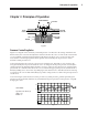
Principles of Operation Chapter 3 Principles of Operation BiPAP EXHAUST VALVE DISC AIR TO PATIENT AIR FROM BiPAP UNIT COIL N S S N PRESSURE CHAMBER MAGNET Figure 1 Pressure Controlling Valve Figure 1 is a diagram of the electrically controlled pressure valve. Based on the setting of the IPAP and EPAP controls, the control circuit adjusts the electrical current in the valve coil.
6 Principles of Operation 3.2 Flow Sensing and Analysis A flow transducer derives a signal proportional to the Total Flow Rate (Vtot) in the patient circuit. From this signal, the system calculates the component of flow, known as the Estimated Patient Flow Rate (Vest), as well as the component derived from leaks in the patient circuit, known as the Estimated Leak Flow Rate (Vleak).
Principles of Operation 2. Tidal Volume Adjustment Inspiratory (VTI) and expiratory (VTE) tidal volumes are determined by the estimated patient flow, and compared on a breath-by-breath basis. If the measured volumes during inspiration differ from expiration, the difference in volume is assumed to be due to an unintentional circuit leak. The baseline • (Vleak) is adjusted in the appropriate direction to reduce the difference in VT - VT on the next breath.
8 Principles of Operation IPAP IPAP PRESSURE PRESSURE EPAP EPAP Shape Signal FLOW Cycle to EPAP Crossover Point Spontaneous Expiratory Threshold FLOW Estimated Patient Flow Trigger to IPAP Crossover Point Figure 6: Spontaneous Expiratory Threshold Figure 5: Shape Signal Tracking the patient's flow pattern with the shape signal provides a sensitive mechanism to trigger to IPAP or cycle to EPAP in response to changing breathing patterns and circuit leaks.
Description of Controls Chapter 4 Description of Controls BiPAP S/T System Front Panel ® ® ® BiPAP S/T I 0 Ventilatory Support System I Power Switch Turns the electrical power to the unit on and off. 0 Air Outlet Accepts a 22 mm connector for smooth inner lumen tubing; also accepts a main flow bacteria filter.
10 Description of Controls Control Panel ! WARNING This is a NON-CONTINUOUS ventilator and is intended to augment patient breathing. IT MUST NOT BE USED AS A LIFE SUPPORT VENTILATOR.
Description of Controls Controls IPAP Control IPAP Inspiratory Positive Airway Pressure. 10 12 14 8 16 6 18 4 20 Active when the Function Selector Knob is in any of these four positions: IPAP, S, S/T, or T. When the unit is delivering IPAP, the adjacent LED is illuminated. Range = 4 - 20 cm H2O. EPAP Control EPAP 10 12 8 Expiratory Positive Airway Pressure. 14 6 16 4 18 20 Active when the Function Selector Knob is in any of these four positions: EPAP, S, S/T, or T.
12 Description of Controls 50 % IPAP Control 70 30 10 90 % IPAP Active when the Function Selector Knob is positioned in the T mode only. This control works in conjunction with the BPM control and determines the fraction of the respiratory cycle spent in IPAP. Range = 10 - 90% NOTE: For % IPAP values greater than 50%, time spent at IPAP will exceed the time spent at EPAP (i.e., an inverse I:E ratio will be delivered).
Description of Controls Elapsed Time Indicator 0000000h Provides resolution to 1/10 hour. Runs only when the power switch is turned ON (I). Power Cord Connector/Fuse Holder Electrical input for the power cord. Use only a Respironics-approved cord set with appropriate grounding. Holds two fuses of appropriate voltage for the country of operation.
Modes of Operation Chapter 5 Modes of Operation Continuous Positive Airway Pressure (CPAP) CPAP can be delivered as follows: Function Selector Knob: EPAP/CPAP Active Control: EPAP Note: The active pressure control being used actually indicates the level of CPAP being delivered. In the CPAP mode, the patient breathes spontaneously at the indicated pressure level. The patient is in total control of both rate and tidal volume.
Modes of Operation Example: IPAP = 15 cm H2O EPAP = 10 cm H2O 60 L/min. Vest 0 60 L/min. 1 second 5 cm H2O P 1 second Figure 2 Example: IPAP = 15 cm H2O EPAP = 4 cm H2O 60 L/min. Vest 0 60 L/min. 1 second 5 cm H2O P 1 second Figure 3 Spontaneous/Timed (S/T): Function Selector Knob: Spontaneous/Timed (S/T) Active Controls: IPAP, EPAP, BPM In the S/T mode, the patient is in control of the respiratory rate as long as it exceeds the BPM setting.
Modes of Operation See the Principles of Operation section for information on trigger and cycle criteria for assisted breaths. Refer to Figures 4 and 5 for examples. Note: When using a recorder, timer triggered breaths in the S/T mode can be identified by an event • marker on the Vest channel. On the recording, there is a deflection below baseline at the initiation of the inspiratory flow. Example: IPAP = 15 cm H2O EPAP = 10 cm H2O BPM = 10 60 L/min. Vest 0 60 L/min.
Modes of Operation In the T mode, the control panel settings determine all movement between the IPAP and EPAP levels. When the interval timer triggers movement to IPAP, the electronic system immediately diverts flow to the patient circuit to establish the IPAP level. The actual flow rate will be dependent upon the pressure differential between the IPAP and EPAP levels and the combined resistance and compliance of the circuit and the patient.
18 Setting Up the BiPAP S/T System Chapter 6 Setting Up the BiPAP S/T System 1. See Figure 16. Connect one end of the patient tubing to the outlet port on the front of the BiPAP unit. In situations where risk of contamination between the user and the BiPAP unit is high, a low resistance, main flow bacteria filter should be placed in-line between the unit and the patient.
Setting Up the BiPAP S/T System Warning: Each time changes are made to the circuit configuration, confirm that delivered pressures are adequate for patient management. Warning: The addition of accessories to the patient circuit (e.g., heated humidifier, bacteria filter, water traps, and additional tube lengths) affects pressure and flow delivery at the patient connection.
20 Administering Oxygen with the BiPAP S/T System Chapter 7 Administering Oxygen with the BiPAP S/T Warning: Oxygen should be administered only on the order of a physician. Warning: Oxygen supports combustion. Oxygen should not be used while smoking or in the presence of an open flame. Warning: Do not add oxygen to the front of the BiPAP S/T System (at the inlet filter opening). Note: When using oxygen, turn the BiPAP S/T System ON (I) before turning on the oxygen source.
Administering Aerosolized Medication with the BiPAP S/T System Chapter 8 Administering Aerosolized Medication with the BiPAP S/T System Small volume nebulizers or adaptors, which allow the use of metered dose inhalers, may be added to the patient circuit. If a small volume nebulizer is used, testing has shown that the liter flow used to drive the nebulizer does not affect the BiPAP S/T System functions.
22 Performance Verification Chapter 9 Performance Verification Warning: Performance verification should be performed prior to each patient use of the BiPAP System. Note: For performance verification, Respironics recommends use of a manometer capable of reading pressures in centimeters of water. 1. Connect the patient circuit following the Set-up Instructions in this manual. Connect the proximal pressure tubing to one of the pressure ports on the mask or exhalation valve. 2.
Performance Verification 8. a. b. c. d. e. f. g. Set the Function Selector Knob to the T mode. Verify that the appropriate LED is illuminated. Verify that the cycling is per control settings. Time the intervals to verify the function. Verify that the BPM setting is 10 and change the % IPAP setting to 50. Observe that the cycling time agrees with the control settings. Change the BPM setting to 15. Observe that the cycling times agree with the control settings.
24 Cleaning Instructions Chapter 10 Cleaning Instructions Cleaning the BiPAP S/T System Caution: Unplug the BiPAP S/T System before cleaning it. Do not immerse it in water or allow any liquid to enter the cabinet. Do not get the filter wet. Caution: Do not clean any part of the system with alcohol or cleaning solutions containing alcohol. Do not clean the system by steam autoclave or gas sterilization methods.
Routine Maintenance Chapter 11 Routine Maintenance Refer to the BiPAP System Service Manual for more complete maintenance information and requirements. Changing the Filter Caution: Failure to replace a dirty filter may cause high operating temperatures, reduce flow, and reduce the output pressure of the BiPAP unit. The white filter on the front of the unit is disposable and must be replaced after thirty days of use or sooner if it seems especially dirty. 1. See Figure 22.
26 Routine Maintenance Changing the Unit Fuses If the unit is not operational when you turn it on, the fuses may need to be replaced. The fuses are located in the back of the unit under the power cord connector. See page 13 for fuse ratings. You may have one of two types of fuse holders. If the fuse holder has tabs on either side, as shown in Figure 25, follow Steps 1 to 4 to replace the fuses. If the fuse holder has a tab on top, as shown in Figure 27, follow Steps 1a to 4a to change the fuses. 1.
Troubleshooting Chapter 12 Troubleshooting The table below lists common problems you may have with your BiPAP S/T System and possible solutions to those problems. If none of the corrective actions listed seem to work, contact your medical equipment distributor. Problem Unit does not operate when turned on. Possible Causes Corrective Action Power cord not firmly connected to the unit or the wall outlet. Check that the power cord is plugged into the unit and into the wall outlet.
28 Abbreviations/Definitions Chapter 13 Abbreviations/Definitions Assist Ventilator A device designed to assist a patient’s spontaneous breathing and to augment ventilation. Auto-trigger Movement to the IPAP level in the S or S/T modes that was not caused by patient effort or the BPM control. BPM Breaths Per Minute. The rate at which the unit will trigger to the IPAP level in the S/T mode if the patient does not initiate a spontaneous trigger.
Abbreviations/Definitions Respiratory Cycle The period of time from the beginning of one inspiration to the beginning of the next inspiration. S Spontaneous mode. The patient triggers all movement from the EPAP to the IPAP level. Movement from the IPAP to the EPAP level is caused by the Spontaneous Expiratory Threshold, by patient effort, or by the maximum spontaneous IPAP time limit. Spontaneous Resulting from patient effort.
30 Specifications Chapter 14 Specifications Functions IPAP: Delivers set pressure continuously EPAP: Delivers set pressure continuously Modes: Spontaneous Spontaneous/Timed Timed CPAP Pressure and Flow Characteristics Pressure Range: IPAP: 4 cm H2O to 20 cm H2O* at ± 60 L/min flow EPAP: 4 cm H2O to 20 cm H2O* at ± 60 L/min flow Pressure controls are coupled so that the unit will not deliver a higher EPAP than IPAP level when the unit is operated in the S, S/T, or T modes.
Specifications Circuit Whisper Swivel II Continuous Leak Rate: Pressure 5 cm H2O 10 cm H2O 15 cm H2O 20 cm H2O Nominal Leak 14 L/min 21 L/min 26 L/min 30 L/min Unit Electrical Requirements: 100 - 130 (60 Hz) or 200 - 260 (50 Hz) VAC Voltage range selected by a rear panel-mounted selector switch Current Consumption: 1 A maximum for 100 - 130 VAC 500 mA maximum for 200 - 260 VAC Physical Characteristics Dimensions: 7 3/4” x 9” x 12 3/16” (20 cm x 23 cm x 31 cm) without accessory cap: 850 cubic inches
32 Limited Warranty Limited Warranty Respironics, Inc. warrants that the BiPAP S/T System, an assist ventilator, will be free from defects of workmanship and materials and will perform in accordance with the product specifications for a period of one year from the date of sale by Respironics, Inc. to the dealer. If the product fails to perform in accordance with the product specifications, Respironics, Inc. will repair or replace, at its option, the defective material or part. Respironics, Inc.