www.respironics.
BiPAP systems are the subject of one or more patents: U.S. Patents #5148802, #5239995, #531937, #5433193; Canadian Patent #2, 024,477; European Patent #EP0425092; German Patent #6902161681.5-08; and other pending U.S. and foreign patents. BiPAP, Harmony, Encore and SmartCard are registered trademarks of Respironics, Inc. © 2003 Respironics, Inc. All rights reserved.
2 TABLE OF CONTENTS CHAPTER 1: PACKAGE CONTENTS ........................................................................... 4 CHAPTER 2: WARNINGS AND CAUTIONS ................................................................. 5 2.1 WARNINGS ................................................................................................ 5 2.2 CAUTIONS ................................................................................................. 6 2.3 INTENDED USE ..........................................
3 CHAPTER 7: HARMONY ALARMS ........................................................................... 34 7.1 INTRODUCTION TO ALARMS ..................................................................... 34 7.2 WHAT TO DO WHEN AN ALARM OCCURS ............................................... 35 7.3 ALARM TABLES ....................................................................................... 37 7.3.2 MEDIUM PRIORITY ALARMS ........................................................... 38 7.3.
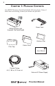
4 CHAPTER 1: PACKAGE CONTENTS Your BiPAP Harmony should include the following items. If any of these items are missing, contact your home care provider. Power Cord BiPAP Harmony with Encore® Pro SmartCard® Ultrafine Filter Filter Cap Pollen Filters www.respironics.com User Manual Flexible Tubing 6 ft. (1.83 m) X 22 mm i.d.
5 CHAPTER 2: WARNINGS AND CAUTIONS WARNING: Indicates the possibility of injury to the user or operator. CAUTION: Indicates the possibility of damage to the device. NOTE: Places emphasis on an operating characteristic. 2.1 WARNINGS • This manual serves as a reference. The instructions in this manual are not intended to supersede the instructions of your health care provider. • You should read and understand this entire manual before using the Harmony.
6 • If you detect any unexplained changes in the performance of the Harmony, if the device is dropped or mishandled, or if the enclosure is broken, seek the assistance of your home care provider. • If water is spilled into the enclosure, discontinue use of the Harmony and remove the power cord. Pour out the excess liquid and allow the unit to dry out. If the device does not function properly, contact your home care provider.
7 2.4 CONTRAINDICATIONS The Harmony should not be used if you have severe respiratory failure without a spontaneous respiratory drive.
8 2.6 INDUSTRY CANADA NOTICE NOTICE: The Industry Canada Label identifies certified equipment. This certification means that the equipment meets telecommunications network protective, operational, and safety requirements as prescribed in the appropriate Terminal Equipment Technical Requirements documents. The Department does not guarantee the equipment will operate to the user’s satisfaction.
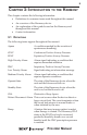
9 CHAPTER 3: INTRODUCTION TO THE HARMONY This chapter contains the following information: • Definitions for common terms used throughout this manual • An overview of the Harmony device • An explanation of the symbols used on the Harmony and throughout this manual • Contact information 3.1 DEFINITIONS The following terms appear throughout this manual: Apnea A condition marked by the cessation of spontaneous breathing.
10 Rise Time The time it takes for the Harmony to change from EPAP to IPAP. You can adjust this time for your comfort. RR Respiratory Rate Spontaneous (S) A bi-level mode which responds to both your inhalation and exhalation by increasing pressure when you start to inhale and decreasing pressure when you start to exhale. There is no automatic delivery of a breath should you not inhale.
11 The circuit, shown in Figure 3–2, consists of: • Circuit tubing to deliver air from the Harmony to your interface (e.g.
12 3.3 SYMBOLS The symbols shown below are used on the Harmony and throughout this manual. Symbol Meaning Attention, consult accompanying documents DC Power Type BF Applied Part Class II (Double Insulated) European CE Declaration of Conformity Notified Body Approval for Standards Compliance Canadian/US Certification 3.4 HOW TO CONTACT RESPIRONICS To have your unit serviced, contact your home care provider.
13 CHAPTER 4: HARMONY CONTROLS AND DISPLAY FEATURES Figure 4–1 shows the location of the Harmony’s control panel, Pressure On/Off button, and breathing circuit connection. Control Panel Breathing Circuit Connection Pressure On/Off Button Figure 4–1 Harmony Front and Top 4.1 PRESSURE ON/OFF BUTTON The Harmony’s Pressure On/Off button, located on the side of the unit, starts and stops the unit’s airflow. Press the button in to turn the airflow on. This puts the Harmony in the Operate state.
14 4.2.1 CONTROL KEYS The control keys on the control panel are shown in Figure 4–2. Display Screen RESET HEAT Alarm Reset Button RAMP Heated Humidifier Button SILENCE User Buttons Ramp Button Alarm Silence Button Figure 4–2 Harmony Control Panel HEAT When the optional REMstar or H2 heated humidifier is prescribed, this button controls the humidifier’s output. Follow the instructions provided with the humidifier.
15 NOTE: If the display backlight is off, the first press of a control key turns the backlight on and does nothing else. The normal key action is suppressed until you press the key a second time. The instructions in this manual assume that the backlight is already on. 4.2.2 ALARM AND POWER INDICATORS Figure 4–3 shows the Harmony’s alarm and power indicators.
16 Figure 4–4 shows the Harmony display screen. Figure 4–4 Harmony Display Screen The information shown on the display screen is defined as follows: ALARM Indicates that the device requires user attention as indicated on the screen. ALERT Indicates that the device requires user attention as indicated on the screen. Not used for Harmony devices. APNEA Indicates that an apnea alarm has occurred or its setting is being displayed. BPM Indicates that a breath rate setting is being displayed.
17 HEAT Indicates that the humidifier is turned on and/or its setting is displayed. HOURS Indicates that the Therapy Hour Meter is being displayed. INSP. TIME Indicates that the inspiratory time setting is being displayed. IPAP Indicates that an IPAP pressure setting is being displayed. LIGHT Indicates that the keypad LED backlight setting is being displayed or is active. NIGHTS Indicates that the session counter is being displayed. Not used for Harmony devices.
18 4.2.4 BREATHING CIRCUIT CONNECTION Figure 4–5 shows where the circuit tubing connects to the Harmony. Patient Interface (Typical) Exhalation Port (Typical) Circuit Tubing Bacteria Filter (Optional) Patient Interface Port Figure 4–5 Breathing Circuit Connection 4.2.5 REAR PANEL Figure 4–6 shows the Harmony’s rear panel. Communications Port DC Inlet SmartCard Connector Filter Cap Figure 4–6 Rear Panel NOTE: The SmartCard Connector is located on the side of the Harmony.
19 The rear panel contains the following: RS-232 Communications Connector This connector accepts the Respironics Communications cable for computer and external modem communication. DC Inlets There are two DC inlets on the rear panel, one for connecting the external AC power supply and another for battery operation using an external DC power supply. Filter Cap The filter cap can be removed to inspect the inlet air filters.
20 CHAPTER 5: SETTING UP THE HARMONY This chapter provides instructions on how to: • Install the air filters • Position the Harmony unit • Connect the breathing circuit • Plug the Harmony in using AC or DC power 5.1 INSTALLING THE AIR FILTERS CAUTION: A properly installed, undamaged foam filter is required for proper operation. The Harmony uses a gray foam filter that is washable and reusable, and an optional white, ultra-fine filter that is disposable.
21 Figure 5–2 Attaching the Filter Cap NOTE: The filter cap should be installed with the air inlet opening at the bottom. See Chapter 8 to clean or replace the filters. 5.2 WHERE TO PLACE THE HARMONY Place the Harmony on its base somewhere within easy reach of where you will use it. Make sure that the air inlet on the rear of the unit is not blocked. Place the unit on a hard, flat surface. If you block the air flow around the unit, the Harmony may not work properly.
22 NOTE: Follow the recommendations of your home care provider for using the optional bacteria filter. Circuit Tubing Bacteria Filter (Optional) Figure 5–3 Connecting the Tubing to the Outlet 2. Connect the open end of the circuit tubing to the exhalation port as shown in Figure 5–4. If you are using a mask that has the exhalation port built into the mask, connect the tubing directly to the mask and skip to Step 4.
23 3. Connect the exhalation port to the mask connector as shown in Figure 5–5. Mask or Other Interface Mask Connector Exhalation Port Figure 5–5 Connecting the Mask 4. Attach the headgear to the mask. See the instructions that came with your headgear. 5.4 COMPLETE HARMONY SETUP Figure 5–6 shows the completed breathing circuit setup for the Harmony.
24 5.5 PLUGGING THE HARMONY IN You can use AC power or DC power to operate the Harmony. WARNING: The DC power option is not intended as a battery backup when using AC power. 5.5.1 USING AC POWER Complete the following steps to operate the Harmony using AC power: 1. Plug the pronged end of the AC power supply’s cord into an electrical outlet. WARNING: Never plug the Harmony AC power supply into an outlet that is controlled by a wall switch. 2.
25 1. Plug the DC boost converter into the rear of the Harmony, as shown in Figure 5–8. 2. Leaving a small amount of slack in the cord, press the cord into the DC cord retainer. 3. Connect the DC cord to the appropriate DC source. See the instructions that came with the DC boost converter for proper DC connections. CAUTION: When DC power is obtained from a vehicle battery, the Harmony should not be used while the vehicle’s engine is running. Damage to the vehicle may occur.
26 CHAPTER 6: OPERATING THE HARMONY This chapter explains how to start the Harmony and change the device settings. 6.1 STARTING THE HARMONY 1. Plug the Harmony in to power up the unit. The Harmony sounds a confirmation alarm and the keypad buttons light up. NOTE: If the alarm does not sound or the buttons do not light up, the Harmony requires servicing. Contact your home care provider. Several screens appear initially during this step: a.
27 c. The third screen to appear is the Blower Hours screen, which displays the blower hours time meter: Figure 6–3 Blower Hours Screen NOTE: With the exception of the Pressure On/Off button, the keypad is inactive during these first three screens. Each of these first three screens appears for approximately 1-3 seconds. d. The next screen that appears is the Standby screen, shown in Figure 6–4. This indicates that the Harmony is in the Standby state. Figure 6–4 Standby Screen 2.
28 3. Put on your mask assembly when the air starts to flow. 4. Make sure that no air is leaking from your mask into your eyes. If it is, adjust the mask and headgear until air stops leaking into your eyes. See the instructions that came with your mask for more information. 5. If you are using the Harmony while sleeping, try placing the tubing from the Harmony over your headboard. This may reduce tension on the mask. NOTE: 6. A small amount of mask leak is normal and acceptable.
29 NOTE: If the display backlight is off, the first press of any key turns the backlight on. Normal key function is suppressed until the key is pressed a second time. NOTE: When changing any setting (except for the Ramp Start Pressure setting), once a maximum setting is reached, the setting rolls back over to the minimum setting, and likewise, once a minimum setting is reached, it rolls back over to the maximum setting provided. For example, the minimum Flex setting is 1 and the maximum is 3.
30 6.2.2 NAVIGATING THE USER DISPLAY SCREENS You can navigate the rest of the user display screens by pressing the Left and Right User keys. You can change the settings on any of the display screens by pressing the Heat and Ramp keys to increase or decrease the setting. Figure 6–7 shows how to navigate the user display screens. Flex Parameter Screen Only displayed if the Flex setting is not equal to zero.
31 6.2.2.1 CHANGING THE FLEX SETTING The Flex setting allows you to adjust the level of air pressure relief that you feel when you exhale during therapy. NOTE: The Flex feature is not prescribed for all users. If the screen shown in Figure 6–8 does not appear on your display, you cannot adjust this setting. To change the Flex setting, complete the following steps: 1. From the Monitoring screen, press the Right User key. The Flex Setting screen appears, as shown in Figure 6–8.
32 To change the rise time setting, complete the following steps: 1. From the Monitoring screen, press the Right User key. The Rise Time Setting screen appears, as shown in Figure 6–9. Figure 6–9 Rise Time Setting Screen 2. Increase or decrease the rise time setting from 1 to 6 by pressing the Heat or Ramp key until you find the right setting. A setting of 1 is the fastest rise time, while 6 is the slowest.
33 Figure 6–10 Ramp Start Setting Screen 2. Press the Heat or Ramp key to increase or decrease the ramp starting pressure as needed. You can adjust the setting from 4.0 cm H2O to the EPAP or CPAP setting. 6.2.2.4 CHANGING THE LED BACKLIGHT SETTING When airflow is turned on and the Harmony is in the Operate state, you can turn the keypad lighting behind the buttons on or off using the LED backlight setting. NOTE: The lights are always on when the airflow is off and the unit is in Standby.
34 CHAPTER 7: HARMONY ALARMS This chapter describes the Harmony alarms and what you should do if an alarm occurs. 7.1 INTRODUCTION TO ALARMS The Harmony provides three alarm levels: high, medium, and low priority. High Priority These alarms require immediate response. The alarm signal consists of a red LED indicator and a sound that is either continuous or a pattern of three beeps, a pause, and then two more beeps. The display has the message ALARM at the top of the screen.
35 In addition to the alarm LED indicators, the keypad also contains alarm Reset and Silence buttons, as shown in Figure 7–2. Alarm Reset Button RESET HEAT RAMP SILENCE Alarm Silence Button Figure 7–2 Alarm Buttons 7.2 WHAT TO DO WHEN AN ALARM OCCURS The following example applies to most alarm conditions. Follow these steps unless otherwise directed by the alarm tables that follow. 1. Look at the alarm indicators and listen to the alarm sound.
36 2. Look at the display for text. Figure 7–4 Sample Alarm Display The word ALARM appears at the top of the screen to indicate an alarm. Additional codes and icons may also appear depending on the type of alarm. 3. Press the Silence key to temporarily silence the alarm (for one minute). 4. Look up the alarm in the alarm tables in Section 7.3 and perform the action specified. 5. Press the Reset key to clear the alarm.
37 7.3 ALARM TABLES The following tables summarize the high priority, medium priority, and low priority alarms. Alarm LED Alarm Sound Display Message Harmony Action Possible Cause Red Flash ••• •• ALARM and PATIENT words flash Operates Breathing circuit is disconnected or has a large leak. Reconnect the circuit or fix the leak. Red Flash ••• •• ALARM and APNEA words flash Operates An apnea event occurred during therapy. Report the alarm to your home care provider.
38 7.3.2 MEDIUM PRIORITY ALARMS Alarm LED Yellow Flash Alarm Sound Display Message Harmony Action ••• DC Power LED Flashes Operates Possible Cause Battery nearly discharged. Your Action Replace the battery. 7.3.
39 CHAPTER 8: TROUBLESHOOTING This chapter describes problems that you may experience with your Harmony or mask and presents possible solutions. Problem Why It Happened What To Do Does not operate when you press thePressure On/ Off button. If the power LED is off, no power at the outlet or the Harmony is unplugged. The air out of the mask is much warmer than usual. The inlet filters may be dirty. The mask feels uncomfortable to wear.
40 Problem Why It Happened What To Do Redness occurs when the mask cushion comes in contact with the skin. This could be due to improper mask fitting or improper mask cleaning. Contact your home care provider for a refitting or a different size mask. Redness occurs when the mask cushion accessory comes in contact with the skin. Irritation or allergic reaction to the mask material. Use a barrier between your skin and the mask, such as 3M’s Microfoam® or Squibb’s Duoderm®. Sore or dry eyes.
41 CHAPTER 9: CLEANING AND MAINTENANCE This chapter provides information on how to clean and maintain your Harmony system. 9.1 CLEANING THE HARMONY Before cleaning or performing any routine maintenance, always make sure the Harmony is not operating and disconnect the Harmony from the power source. NOTE: The following cleaning instructions are for the Harmony only. To clean the accessories, refer to each accessory’s instruction sheet.
42 Figure 9–1 Removing the Filter 3. Remove the filters from the enclosure as shown in Figure 9–2. The top filter is the reusable gray foam filter. The bottom filter is the optional disposable, white, ultra-fine filter. Reusable Gray Foam Filter Disposable Ultra-fine Filter Figure 9–2 Removing the Air Filters 4. Check the filters to see if they are dirty or torn. 5. If needed, wash the foam filter in warm water and a mild detergent. Rinse the filter thoroughly to remove all detergent residue.
43 8. Replace the filter cap. Contact your home care provider to order filters. NOTE: To clean the breathing circuit accessories, refer to each accessory’s instruction sheet.
44 CHAPTER 10: ACCESSORIES There are several accessories you can use with the Harmony. 10.1 ADDING A HUMIDIFIER The REMstar Heated Humidifier, REMstar Pass-over Humidifier, and H2 Heated Humidifier are available from your home care provider. The humidifiers may reduce nasal dryness and irritation by adding moisture (and heat, if applicable) to the airflow. CAUTION: For safe operation, the humidifier must always be positioned below the circuit connection at the mask and the air outlet on the Harmony.
45 CHAPTER 11: SPECIFICATIONS ENVIRONMENTAL Operating Storage Temperature 5ºC to 35 ºC -20ºC to 60ºC Relative Humidity 15 to 95% (non-condensing) 15 to 95% (non-condensing) Atmospheric Pressure (5600 feet to sea level) 83 to 102kPa PHYSICAL Dimensions: 4.4” H 9.75” L x 6.625” W x Weight: Approximately 4.1 lb ELECTRICAL AC Voltage: 100 to 240 V, 50/60 Hz DC Voltage: 12 V (when operated with the external DC power supply) AC Current: 1.25 A maximum DC Current: 3.
46 Modes of Operation: Continuous Electromagnetic Compatibility: The Harmony meets the requirements of EN 60601-1-2. Fuses: There are no userreplaceable fuses. PRESSURE 4 to 30 cm H2O Output: CONTROL ACCURACY Parameter Range Accuracy IPAP 4 to 30 cm H2O ± 2.5 cm H2O* EPAP 4 to 25 cm H2O ± 2.5 cm H2O* CPAP 4 to 20 cm H2O ± 2.5 cm H2O* Breath Rate 0 to 30 BPM Greater of ± 1 BPM or ± 10% of the setting Timed Inspiration 0.5 to 3.
47 LIMITED WARRANTY Respironics, Inc. warrants that the BiPAP Harmony system shall be free from defects of workmanship and materials and will perform in accordance with the product specifications for a period of two (2) years from the date of sale by Respironics, Inc. to the dealer. If the product fails to perform in accordance with the product specifications, Respironics, Inc. will repair or replace – at its option – the defective material or part. Respironics, Inc.
48 Index Provider Manual
1012892 JH 3/14/03