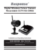
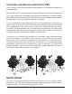
Digital Wireless Colour Camera Recordable CCTV Kit CWD2 Installation and Operating Instructions Lines open Monday to Friday 9.00am to 5.00pm. Calls charged at local rates. !" These instructions should be retained in a safe place for future reference.
CONTENTS 1. INTRODUCTION—3 2. KIT CONTENTS—6 3. INSTALLATION—8 3.1 Contents and Connections 8 3.2 Powering up the system 9 3.3 Setting the Camera Channel (Optional) 3.4 Pairing the Camera to Receiver (Optional) 3.5 Camera Installation 11 10 10 4. RECEIVER AND IR REMOTE PANEL INTRODUCTION—12 5. SYSTEM INTRODUCTION—13 5.1 Icon Functions 5.2 System Menu 13 14 6. System Operation —16 6.1 Camera Setup 16 6.2 Recorder Setup 19 6.3 Event List 21 6.4 System Setup 23 6.5 Alarm Buzzer 26 6.6 Pan Tilt Zoom 27 6.
1. INTRODUCTION The Digital Wireless Colour Camera Recordable CCTV Kit is a wireless security system designed to view and capture video clips of any motion viewed by the wireless camera and store them in on a micro SD memory card. The wireless camera supplied is colour, ! Please read before you start: Always use discretion when installing CCTV survillance equipment especially when there is perceived policy.
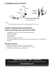
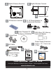
PLANNING YOUR LAYOUT: DVR Receiver Camera 1 20mm diameter cable hole TV/Monitor (to allow camera cable and connector to pass through) Front Door Ensure the distance from camera to power outlet does not exceed the length of the camera power adapter cable Camera 2 NOTE: # $% '*+ SAFETY AND INSTALLATION TIPS: Camera and Receiver with built in DVR " " " " " " keep away from heat sources and high temperature places Avoid direct sunlight Avoid h
Camera(s) and Receiver with built in DVR Do not attempt to open the units with the power adaptor plug connected to avoid any risk of personal injury. When installing CCTV camera(s), always follow manufacturer's advice when using power tools, steps, ladders, etc. and wear suitable protective equipment (e.g. safety goggles) when drilling holes. Before drilling holes through walls check for hidden electricity cables and water pipes. The use of cable/pipe detector is advisable.
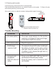
2. KIT CONTENTS A 1 x Digital Wireless Receiver B 1 x Digital Wireless Camera C ' ? @$ $ Q [ Q$\+\* D 2 x 5V/1A Power Adapter for Camera and Receiver E 1 x Camera Stand F 1 x Fixings Pack G 1 x Video Playback PC Software (CD-ROM) H 1 x AV Cable for TV output I Trouble Shooting page 9 or call the Customer Helpline available Monday to Friday 9.00 am to 5.00pm.
A B Digital Wireless Receiver Digital Wireless Camera LINK PWR. E C IR Remote Controller G F H 5V 1A Power Adapter for Camera and Receiver Video Playback PC Software (CD-ROM) K Fixings Pack 2GB Micro SD Memory Card and Adaptor Power Supply Extension Cable for Cameras (1.
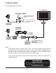
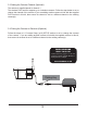
3. INSTALLATION 3.1 Contents and Connections TV / MONITO R WIRELESS CAMERA Screw the Camera Antenna clockwise on to the back of Camera Screw the Camera Bracket clockwise on to the lower body of the Camera to Wireless Cammera Camera Power Supply Adaptor Video Signal to RCA Input WIRELESS RECEIVER RESET DC 5V/1A AV OUT Turn power on here Receiver Power Supply Adaptor Connect to DC 5V/1A por t on Wireless Receiver Connect to 3.
3.2 Powering up the system @ ][$ Press and Hold the power key for one second to power on the system. To Power off, press and hold the power key for two seconds. After system power on, adjust the camera viewing position again if necessary.
3.3 Setting the Camera Channel (Optional) The camera is supplied preset to channel 1. The wireless DVR receiver supports up to 4 wireless cameras. Follow the step below to set or change the channel of the camera. If you are adding another camera to link with the supplied DVR receiver in this kit, then ensure its channel is set to a different channel to the existing camera(s). 3.4 Pairing the Camera to Receiver (Optional) Follow the steps in 6.1 Camera Setup (p.
3.5 Camera Installation Attach Stand to Mounting Surface C B A.Secure camera stand on the wall B. Loosen the thumb screw C.Adjust the camera to the correct viewing position then secure the joint with T-bolt.
4. RECEIVER AND IR REMOTE PANEL INTRODUCTION IR REMOTE RECEIVER 12 9 3 1 2 LINK PWR.
5. SYSTEM INTRODUCTION 5.1 Icon Functions 1 01-01-2011 AM12:54:29 (Display Icon) 1. 2. 3. 4. 5. 6. 7. 8. 9.
5.2 System Menu [Main Menu] Press MENU to enter main menu. After entering [MAIN MENU] system will highlight EVENT LIST by default. System will idle in [MAIN MENU] for 2 minutes before exiting [MAIN MENU].
EVENT LIST Press MENU to enter EVENT LIST SYSTEM SETUP Press MENU to enter SYSTEM SETUP ALARM BUZZER Press MENU to turn ALARM BUZZER ON / OFF for when motion is detected PAN TILT ZOOM Trouble Shooting page 9 or call the Customer Helpline available Monday to Friday 9.00 am to 5.00pm.
SCAN ACTIVATED CAMERAS Press MENU to scan activated cameras in full screen mode. MEMORY CARD OVERWRITE Press MENU to set memory card overwrite ON or OFF. 6. System Operation 6.1 Camera Setup Select CAMERA SETUP, press MENU key once to enter sub-menu.
} ~ ' } @$@ $@# Q$ %% Camera Pairing With PAIRING section highlighted, press MENU key once to begin camera pairing (pair LED on camera will blink once ). Then press and release the pairing key on the camera as shown in page 10. The link LED will stay on after camera is linked.
Camera Brightness Adjustment $@# ! ~ Press ESC to return to main menu. Camera Activation Q#@[#@ ! ~ Press ESC to return to main menu. NOTE: Ensure the cameras are paired to the receiver for SCAN or QUAD to function properly (camera "ON" can only be selected when camera has been paired to system.).
6.2 Recorder Setup Record Schedule } ~ } # recording options available to chose from. First highlight the time period and press MENU key to switch between different recording mode. M: MOTION (REC only when motion detected) S: SCHEDULE (record between selected times for each day) C: MANUAL (manual REC) The system will record video from all 4 channels simultaneously with MOTION, SCHEDULE and MANUAL record modes.
Motion Detection Sensitivity Select RECORDER SETUP, press MENU to enter.
Record Time Select RECORDER SETUP, press MENU to enter. } ~ $Q$] #@ } \ * '+ @! } Press ESC to save and exit 6.
(1) Starting / Time: Start Time = PM10:33 End Time = PM10:43 \ # Q ' Q]} Q ' #@ Q '! \! } Q Q NOTE: The channel indicator 1, 2, 3, 4 in SOLID square indicate the following: - In MOTION (M): channel triggered. - In SCHEDULE (S): channel selected by user. - In MANUAL (C): channel selected by user.
6.4 System Setup Date and Time Select SYSTEM SETUP, press MENU to enter. } ~ ]# ] #@! } } $ # ]# }$ @}#! ~ } Press ESC to save and exit TV Out System (NTSC/PAL) Use the supplied A/V output cable to display the system on a TV/monitor if required. Select SYSTEM SETUP, press MENU to enter.
Power Saving (Model Dependent) (5 Minutes) (10 Minutes) (Always ON) Select SYSTEM SETUP, press MENU to enter. } ~ $ [@ } Q$ %% %#$ * @}# @] Q$ %% %#$ '+ @}# @] Q$ ! } Press ESC to save and exit. NOTE: POWER SAVING is for model with built-in LCD ONLY. Multi Channels Idle Display This is used to set the display mode for each camera channel when the display is left idle.
(Display QUAD mode) (5 sec Intervals) (10 sec Intervals) (15 sec Intervals) Select SYSTEM SETUP, press MENU to enter. } ~ }#@ Q @] ]@ } ]@ }] ]}$@ @] # * Q @#$[ # '+ Q @#$[ # '* Q @#$[! } Press ESC to save and exit. NOTE: (1) Camera ON/OFF setting in CAMERA SETUP section will affect which camera(s) can be displayed during IDLE DISPLAY.
Default Select SYSTEM SETUP, press MENU to enter. } ~ ]%}# } # $#$! } selection and system will restore to factory default. 6.5 Alarm Buzzer Select ALARM BUZZER, press MENU to turn buzzer ON or OFF. When motion is detected by a camera, then a buzzer sound will be triggered by the monitor.
6.6 Pan Tilt Zoom Select PAN TILT ZOOM, press MENU once to enter ZOOM mode, press MENU again to zoom in (2X). = ! ~ < < Press MENU to zoom out. @ = ' ! ~ < Press ESC to exit ZOOM. Select SCAN ACTIVATED CAMERAS, press MENU once to begin camera scan mode. NOTE: (1) Camera ON/OFF setting in CAMERA SETUP section will affect which camera(s) can be displayed during IDLE DISPLAY. See p.25 for the display interval setup.
6.7 Memory Card Overwrite When the memory is full, by enabling this function will allow you to overwrite the earlist Select MEMORY CARD OVERWRITE, press MENU once to activate overwrite function and press MENU again to de-activate. NOTE: (1) One of the following examples will appear on display screen a. 1.89GB - space available on memory card. b. ERROR - either memory card is missing, locked or damaged.
7.PLAYBACK SOFTWARE # \ Q ] < < < 7.1 Sec24 Media Player Introduction 1 2 3 4 5 6 1. 2. 3. 4. 5. 6. 7. 8. 9. 10. 11. 12. 13.
7.2 Installation Insert the CD into the CD-ROM of the PC. Click on MY COMPUTER, double click on the drive where the CD-ROM is assigned by the PC (for example: E;\). In this drive you will find the following icon. Please read the following steps to complete installation. 7.2.1 If Window 7 is running on your PC, please right click on icon “20111027_ Sec24 Media Player_v1.0.9.44” and select “Run as administrator” option first to begin installation.
7.2.2 The following error message will appear if you did not select “Run as 7.2.3 Double click the icon to start installation process.
7.2.4 Click “Next” and the following window will appear on the screen. 7.2.5 The following window will appear on the screen after installation is complete. Click “Finish” to complete the installation.
7.3.1 Double click Sec24 Media Player icon on the desktop to start the software Trouble Shooting page 9 or call the Customer Helpline available Monday to Friday 9.00 am to 5.00pm.
7.3.2 Click on “Load” to import and playback previous recorded files (SNX files) already stored on your PC. NOTE: < Q @ Q memory card reader then use the supplied memory card adaptor.
7.4 Channel Disable / Enable Select During playback, all four channels will playback at once. For privacy concern, user is able to manually disable audio channel and/or video channel(s).
jGX h jGY jGz i jGZ w jG[ z jY jZ j[ jX jY jZ j[ YG \G XWG jX tG yGz n zkGjGm tGh yG{ lGs OspmvP k o m w Gt tt kk \G XWG ul}ly x|hk zG\Gz zGXWGz u{zjGv|{ whsGv|{ ooGOhtVwtP tt kGVG{ wGz z z zGX\Gz pGk s k
Camera Receiver Remote Maximum Channels 4 1 Communication Range 150 metres in open space 2m Monitor Resolution 800X480 N/A Camera Resolution 640X480 N/A Operating Temperature -10°C ~ 50°C -10C ~ 50C Operating Voltage DC 5V / 1A 3V Current Consumption 550mA(max) 860mA(mas) Night Vision 0.003mA 5-8m N/A Dimension 123x65x65 mm 200x122x25 mm 86x40x7 Battery N/A N/A 3V CR2025 Lithium Coin Cell 10.Total Recording Time for Memory Cards (32GB max.
Disposal and Recycling (Directive 2002/96/EC) # ¢ ] < It should not be disposed of with other household or other commercial waste. At the end of its useful life the packaging and product should be disposed of via a suitable recycling centre. For information on available facilities, please contact your local authority or retailer from where the product was purchased.