Digital Wireless Colour Camera Recordable CCTV Kit CWD3 Installation and Operating Instructions YOUR HELPLINE 0844 736 9149 Lines open Monday to Friday 9.00am to 5.00pm. Calls charged at local rates. www.friedland.co.uk These instructions should be retained in a safe place for future reference.
CONTENTS 1. INTRODUCTION—3 2. KIT CONTENTS—6 3. INSTALLATION—8 3.1 Contents and Connections 8 3.2 Powering up the system 9 3.3 Setting the Camera Channel (Optional) 3.4 Pairing the Camera to Receiver (Optional) 3.5 Camera Installation 11 10 10 4. MONITOR PANEL INTRODUCTION—12 5. SYSTEM INTRODUCTION—13 5.1 Icon Functions 5.2 System Menu 13 14 6. System Operation —16 6.1 Camera Setup 16 6.2 Recorder Setup 19 6.3 Event List 21 6.4 System Setup 23 6.5 Alarm Buzzer 26 6.6 Pan Tilt Zoom 27 6.
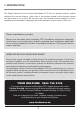
1. INTRODUCTION The Digital Wireless Colour Camera Recordable CCTV Kit is a wireless security system designed to view and capture video clips of any motion viewed by the wireless camera and store them in on a micro SD memory card. The wireless camera supplied is colour, weatherproof and suitable for day/night use for the protection of your home or office, etc. Please read before you start: Always use discretion when installing CCTV survillance equipment especially when there is perceived policy.
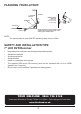
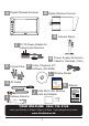
PLANNING YOUR LAYOUT: 7" LCD DVR Receiver Camera 1 20mm diameter cable hole TV/Monitor (to allow camera cable and connector to pass through) Front Door Camera 2 Ensure the distance from camera to power outlet does not exceed the length of the camera power adapter cable NOTE: The camera has an open field RF operating range of up to 150m.
Camera(s) and DVR Do not attempt to open the units with the power adaptor plug connected to avoid any risk of personal injury. When installing CCTV camera(s), always follow manufacturer's advice when using power tools, steps, ladders, etc. and wear suitable protective equipment (e.g. safety goggles) when drilling holes. Before drilling holes through walls check for hidden electricity cables and water pipes. The use of cable/pipe detector is advisable.
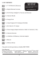
2. KIT CONTENTS YOUR HELPLINE 0844 736 9149 A 1 x 7" LCD Monitor (Receiver) B 2 x Digital Wireless Cameras C 3 x 5V/1A Power Adapter for Camera and Receiver D 2 x Camera Stands E 2 x Fixings Pack F 1 x Video Playback PC Software(CD-ROM) G 1 x AV Cable for TV Output H 2 x Power Supply Adaptor Extension Cable for Cameras (1.8m) I Trouble Shooting page 9 or call the Customer Helpline available Monday to Friday 9.00 am to 5.00pm. www.friedland.co.
A B Digital Wireless Receiver Digital Wireless Camera D C 5V/1A Power Adapter for Camera and Receiver H E Camera Stand Fixings Pack F Power Supply Extension Cable for Cameras (1.8m) Video Playback PC Software (CD-ROM) L Window Sticker C C T V G I AV Cable K J Camera Antenna 2GB Micro SD Memory Card and Adaptor Manual Digital Wireless Colour Camera Recordable CCTV Kit CWD3 Installation and Operating Instructions YOUR HELPLINE 0844 736 9149 Lines open Monday to Friday 9.00am to 5.00pm.
3. INSTALLATION 3.
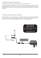
3.2 Powering up the system Insert the memory card into the DVR if not already fitted Press and Hold power key for one second to power hold the power. Press and hold the power key for two seconds to power off the system. After system power on, adjust the camera viewing position again if necessary. Micro SD card slot on 7" LCD DVR ON/OFF power button The 7" LCD monitor DVR is fitted with a rechargeable battery and can operate for up to 4 hours (in power save mode) on battery power once fully charged.
3.3 Setting the Camera Channel (Optional) The wireless cameras will be supplied preset to channel 1 and channel 2. The wireless monitor supports up to 4 wireless cameras. Follow the step below to set or change the monitor channel of the camera. If you are adding another camera to link with the supplied monitor in this kit, then ensure its channel is set to a different channel to the existing camera(s). 3.4 Pairing the Camera to Receiver (Optional) Follow the steps in 6.1 Camera Setup (p.
3.5 Camera Installation Attach Stand to Mounting Surface C B A.Secure camera stand on the wall B. Loosen the thumb screw C.Adjust the camera to the correct viewing position then secure the joint with T-bolt.
4.
5. SYSTEM INTRODUCTION 5.1 Icon Functions (Display Icon) 1. 2. 3. 4. 5. 6. 7. 8. 9. Signal Indicator 1 Channel Indicator Recording Indicator Audio Channel Indicator Display mode QUAD Display Scan Display 1 Single Display Audio Volume (Seven volume levels) = Full Volume = 1/2 Volume = Mute Monitor Power Indicator Power indicator will indicate 100% when adaptor in use or the battery is fully charged. Power indicator will indicate much battery power power available for operation in blocks.
5.2 System Menu [Main Menu] Press MENU to enter main menu. After entering [MAIN MENU] system will highlight EVENT LIST by default. System will idle in [MAIN MENU] for 2 minutes before exiting [MAIN MENU]. Use ▲▼◄► to select, Press MENU to confirm selection and to enter sub-menu.
EVENT LIST Press MENU to enter EVENT LIST SYSTEM SETUP Press MENU to enter SYSTEM SETUP ALARM BUZZER Press MENU to turn ALARM BUZZER ON / OFF for when motion is detected PAN TILT ZOOM YOUR HELPLINE 0844 736 9149 Trouble Shooting page 9 or call the Customer Helpline available Monday to Friday 9.00 am to 5.00pm. www.friedland.co.
SCAN ACTIVATED CAMERAS Press MENU to scan activated cameras in full screen mode. MEMORY CARD OVERWRITE Press MENU to set memory card overwrite ON or OFF. 6. System Operation 6.1 Camera Setup Select CAMERA SETUP, press MENU key once to enter sub-menu.
Use▼▲to select the camera to set up (1-4). Use◄►to select [PAIRING] [BRIGHTNESS] [CAMERA ON/OFF] Camera Pairing With PAIRING section highlighted, press MENU key once to begin camera pairing (pair LED on camera will blink once and following with LED blinking continuously indicating data transmission in process. System will confirm pairing process is successful with "PAIRED" displaying on screen. System will indicate pairing process failed with "PAIRING FAIL" displaying on screen.
Camera Brightness Adjustment With BRIGHTNESS section highlighted, use ▼▲ to adjust camera brightness. Press ESC to return to main menu. Camera Activation With ACTIVATION section highlighted, use ▼▲ to enable or disable camera. Press ESC to return to main menu. NOTE: Ensure the cameras are paired to the receiver for SCAN or QUAD to function properly (camera "ON" can only be selected when camera has been paired to system.).
6.2 Recorder Setup Record Schedule Use▲▼◄► to select and press MENU to enter schedule setup.There are three different recording options available to chose from. First highlight the time period and press MENU key to switch between different recording mode. M: MOTION (REC only when motion detected) S: SCHEDULE (record between selected times for each day) C: MANUAL (manual REC) The system will record video from all 4 channels simultaneously with MOTION, SCHEDULE and MANUAL record modes.
Motion Detection Sensitivity Select RECORDER SETUP, press MENU to enter.
Record Time Select RECORDER SETUP, press MENU to enter. Use ▲▼ to select RECORD TIME section Use ◄► to highlight recording period: 2 Min / 5 Min / 10 MIN, press MENU to confirm Press ESC to save and exit 6.3 Event List Playback Use ◄► to highlight desired DATE index for playback Press MENU to confirm selection and enter selected folder. Press ◄► to select Hour (each block represent one hour time), Press MENU to enter Use ◄► to highlight desired HOUR for playback.
(1) Starting / Time: Start Time = PM10:33 End Time = PM10:43 (2) The type of recorded file (Schedule / Motion / Manual) is indicated by: = Channel 1 is SCHEDULE recorded file = Channel 1 is MOTION recorded file =Channel 1, 2, 3 and 4 are MANUAL (C = Continous) recorded files NOTE: The channel indicator 1, 2, 3, 4 in SOLID square indicate the following: - In MOTION (M): channel triggered. - In SCHEDULE (S): channel selected by user. - In MANUAL (C): channel selected by user.
6.4 System Setup Date and Time Select SYSTEM SETUP, press MENU to enter. Use ▲▼ to highlight DATE AND TIME, press MENU to enter. Use ◄► to highlight adjust: YEAR / MONTH / DATE / HOUR / MINUTE, use ▲▼ to adjust each section and press MENU to confirm adjustment. Press ESC to save and exit TV Out System (NTSC/PAL) If required, use the supplied A/V output cable to display the system on a TV/monitor. Select SYSTEM SETUP, press MENU to enter. Use ▲▼ to select TV OUTPUT.
Power Saving (5 Minutes) (10 Minutes) (Always ON) Select SYSTEM SETUP, press MENU to enter. Use ▲▼ to select POWER SAVING Use ◄► to select SCREEN OFF AFTER 5 MINUTES IDLE / SCREEN OFF AFTER 10 MINUTES IDEL / SCREEN ALWAYS ON, press MENU to confirm setting. Press ESC to save and exit. Multi Channels Idle Display This is used to set the display mode for each camera channel when the display is left idle.
(Display QUAD mode) (5 sec Intervals) (10 sec Intervals) (15 sec Intervals) Select SYSTEM SETUP, press MENU to enter. Use ▲▼ to select MULTI CHANNELS IDLE DISPLAY. Use ◄► to select: DISPLAY QUAD DURING IDLE / AT 5 SEC INTERVALS / AT 10 SEC INTERVALS / AT 15 SEC INTERVALS, press MENU to confirm selection. Press ESC to save and exit. NOTE: (1) Camera ON/OFF setting in CAMERA SETUP section will affect which camera(s) can be displayed during IDLE DISPLAY.
Default Select SYSTEM SETUP, press MENU to enter. Use ▲▼ to select DEFAULT. Use ◄► to select the system language for SYSTEM RESTORE, press MENU to confirm selection and system will restore to factory default. NOTE: While SYSTEM RESTORE icon highlighted, system firmware version will be displayed (example: VER:11.06.11-21:13:09) 6.5 Alarm Buzzer Select ALARM BUZZER, press MENU to turn buzzer ON or OFF. When motion is detected by a camera, then a buzzer sound will be triggered by the monitor.
6.6 Pan Tilt Zoom Select PAN TILT ZOOM, press MENU once to enter ZOOM mode, press MENU again to zoom in (2X). When zooming in, use ▲▼ ◄► to select various view areas. Press MENU to zoom out. In zoom out (1X), use ▲▼to change available channel Press ESC to exit ZOOM. Select SCAN ACTIVATED CAMERAS, press MENU once to begin camera scan mode. NOTE: (1) Camera ON/OFF setting in CAMERA SETUP section will affect which camera(s) can be displayed during IDLE DISPLAY. See p.25 for the display interval setup.
6.7 Memory Card Overwrite When the memory is full, by enabling this function will allow you to overwrite the earlist files with the recent ones. Select MEMORY CARD OVERWRITE, press MENU once to activate overwrite function and press MENU again to de-activate. NOTE: (1) One of the following examples will appear on display screen a. 1.89GB - space available on memory card. b. ERROR - either memory card is missing, locked or damaged.
7.PC PLAYBACK SOFTWARE The Sec24 Media Player is specifically designed to playback recorded files from the Micro SD card provided video files have been recorded by the system. 7.1 Sec24 Media Player Introduction 1 2 3 4 5 6 1. 2. 3. 4. 5. 6. 7. 8. 9. 10. 11. 12. 13.
7.2 Installation Insert the CD into the CD-ROM of the PC. Click on MY COMPUTER, double click on the drive where the CD-ROM is assigned by the PC (for example: E;\). In this drive you will find the following icon. Please read the following steps to complete installation. 7.2.1 If Window 7 is running on your PC, please right click on icon “20111027_Sec24 Media Player_v1.0.9.44” and select “Run as administrator” option first to begin installation.
7.2.2 The following error message will appear if you did not select “Run as administrator” option first before starting the installation. 7.2.3 Double click the icon to start installation process.
7.2.4 Click “Next” and the following window will appear on the screen. 7.2.5 The following window will appear on the screen after installation is completed. Click “Finish” to complete the installation.
7.3 Playback recorded file(s) 7.3.1 Double click the Sec24 Media Player icon on the desktop to start the software YOUR HELPLINE 0844 736 9149 Trouble Shooting page 9 or call the Customer Helpline available Monday to Friday 9.00 am to 5.00pm. www.friedland.co.
7.3.2 Click on “Load” to import and playback previous recorded files (SNX files) already stored on your PC. NOTE: You will first need to save the files from the Micro SD card to the PC first. If your PC has a memory card reader then use the supplied memory card adaptor.
7.4 Channel Disable / Enable Select During playback, all four channels will playback at once. For privacy concern, user is able to manually disable audio channel and/or video channel(s).
8.
9.Product Specification Camera Receiver Maximum Channels Communication Range Monitor Resolution Camera Resolution 4 150 metres in open space 800X480 640X480 Operating Temperature Operating Voltage Curren Consumption Night Vision Dimension -10°C ~ 50°C DC 5V / 1A 123x65x65 mm 200x122x25 mm Battery N/A 3.7V 1800mAH (LI-ON) 550mA(max) 860mA(max) 5-8m 10.Total Recording Time for Memory Cards (32GB max.
Disposal and Recycling (Directive 2002/96/EC) The product is classified by the Waste Electrical or Electronic Equipment (WEEE) Directive. It should not be disposed of with other household or other commercial waste. At the end of its useful life the packaging and product should be disposed of via a suitable recycling centre. For information on available facilities, please contact your local authority or retailer from where the product was purchased.