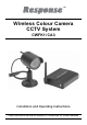
Wireless Colour Camera CCTV System CWFK1 / CA3 Installation and Operating Instructions These instructions should be retained in a safe place for future reference.
CONTENTS 1 INTRODUCTION 3 4.3 Setting the Camera Channel (Optional) 9 2 KIT CONTENTS 4 4.4 Setting the Receiver Channel (Optional) 10 3 INSTALLATION 5 4.5 Night Vision 10 4.6 Camera and Interference 10 3.1 3.2 3.3 Direct Connection of the Receiver to the TV 5 Connection of the Receiver to a VCR / DVR 6 Wireless Camera Installation 4 VIEWING THE CAMERA 5 TROUBLESHOOTING 12 7 6 TECHNICAL SPECIFICATION 13 8 7 ACCESSORIES IN THE RANGE 14 4.
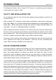
INTRODUCTION Section 1 The Response Wireless Colour Camera CCTV System is a monitoring system designed to help protect your home or office. SAFETY AND INSTALLATION TIPS: Do not attempt to open the units with the power adaptor plug connected to avoid any risk of personal injury. When installing CCTV camera(s), always follow manufacturer’s advice when using power tools, steps, ladders, etc. and wear suitable protective equipment (e.g. safety goggles) when drilling holes.
KIT CONTENTS Section 2 CWFK1: 1 x Wireless Colour Camera 1 x Wireless Receiver unit 1 x Video output cable for wireless receiver to TV 1 x Wireless Camera power supply adaptor (12VDC/300mA) 1 x Wireless Receiver power supply adaptor (12VDC/300mA) 1 x Camera fixing kit - wall plugs and screws 1 x Window stickers 1 x Installation and operating manual CA3: 1 x Wireless Colour Camera 1 x Wireless Camera power supply adaptor 1 x Camera fixing kit - wall plugs and screws 1 x Window sticker 1 x Installation and
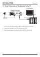
INSTALLATION Section 3 3.1 Direct Connection of the Receiver to the TV TV / MONITOR WIRELESS RECEIVER DC12V POWER VIDEO AV Input Yellow Connector (VIDEO) DVRs Power Supply Adaptor INPUT 1 INPUT 2 1. Connect the video cable and power adaptor’s output plug into the receiver. 2. Connect the video cable to the RCA video input on the TV. 3. Plug the power adaptor into the mains socket (240VAC) and switch ON.
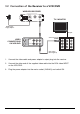
3.2 Connection of the Receiver to a VCR / DVR WIRELESS RECEIVER DC12V POWER VIDEO TV / MONITOR DVRs Power Supply Adaptor AV Input Yellow Connector (VIDEO) VIDEO CONNECTIONS ON VCR/DVR INPUT 1 INPUT 2 INPUT OUTPUT Video Cable (Not Supplied) 1. Connect the video cable and power adaptor’s output plug into the receiver. 2. Connect the other end of the supplied video cable into the RCA video INPUT on the VCR / DVR. 3. Plug the power adaptor into the mains socket (240VAC) and switch ON.
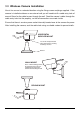
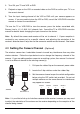
3.3 Wireless Camera Installation Mount the camera in a selected location using the fixing screws and plugs supplied. If the camera is installed outdoors on an external wall you will need to drill a cable entry hole of around 15mm for the cable to pass through the wall. Feed the camera’s cable through the cable entry hole into the property, so that all connections are made inside. Ensure that there is a mains power socket internally located near to the camera for power.
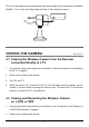
The sun shade hood can be removed from the camera body and re-attached for installation flexibility. This is done by sliding along the body of the camera as shown. 2.4 GHz Weather-proof VIEWING THE CAMERA Section 4 4.1 Viewing the Wireless Camera from the Receiver connected directly to a TV 1. Connect the camera and receiver as described in ‘Direct Connection of the Receiver to the TV’ on page 5. 2. Power up the receiver and camera. 3. Turn ON your TV. 4.
3. Turn ON your TV and VCR or DVR. 4. Playback a tape on the VCR or recorded video on the DVR to confirm your TV is on the correct channel. 5. Tune the input viewing channel of the VCR or DVR until your camera appears on screen. If you are unable to tune the VCR or DVR, consult the VCR / DVR instruction manual or contact its manufacturer *. * To tune the TV or VCR / DVR to view the camera, press the button associated with, Source, Line In, L1, L2, AUX, A / V, channel 0 etc.
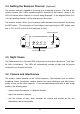
4.4 Setting the Receiver Channel (Optional) The wireless receiver is capable of receiving up to 4 separate channels. The front of the wireless receiver has 4 LEDs representing the 4 channels of the receiver. When lit, the LED will indicate which channel is currently being displayed. In the diagram below CH1 is lit up indicating channel 1 will be displayed on the screen. The wireless receiver allows you to manually switch between active channels by pushing the SET button.
- dense materials such as concrete or metal will impede the wireless signal; move the camera and/or receiver away from dense materials. A metal radiator is an example. - if possible keep the camera and receiver away from or move conflicting devices such as wireless routers, microwaves, cordless phones. - make sure all Cameras are set to different channels. - disconnect all other wireless devices to find out which is causing the problem and adjust your setup accordingly.
TROUBLE SHOOTING Section 5 PROBLEM SOLUTION I can’t see the Camera Ensure the camera and receiver are plugged in. on my TV and the TV / VCR / DVR is tuned to the correct input channel as described on page 9. A white image appears at night The camera’s infra-red LEDs shine invisible light that reflects of surfaces such as glass causing white light. Place the camera on the other side of windows or place the lens flush against the surface to try to improve the night vision or place in a well lit area.
TECHNICAL SPECIFICATION Section 6 ITEM WIRELESS CAMERA Image sensor 1/3” CMOS Pixel resolution PAL: 628 x 582 NTSC: 510 x 492 380 TV lines Lens size 6mm Viewing angle 60° Night vision range Up to 7m Number of infra-red LEDs 11 Day / night mode Colour during the day / switches to B&W at night Minimum illumination 5 Lux when the IR lamps are turned on Signal Analogue Maximum transmission range 100m (open field range) Operating frequency 2.4000 GHz – 2.
ACCESSORIES IN THE RANGE Section 7 There are a range of accessories available in the Response CCTV product range to expand your system: CWK1 Wired Colour Camera CCTV Kit CA1 2 Channel Digital Video Image Recorder CA2 LCD Screen for Wireless / Wired CCTV Kits CA3 Wireless Colour Accessory Camera (requires CWFK1 CCTV KIT to operate) CA5 Professional Heavy Duty Camera CCTV Kit CA6 Dummy Professional Heavy Duty Camera CA7 4 Channel DVR Recorder Kit CA8 Wired Internal Colour Dome Camera CCTV Kit
DISPOSAL – RECYCLING INSTRUCTIONS Directive (2002/96/EC) This product is classified by the Waste Electrical or Electronic Equipment (WEEE) Directive. It should not be disposed of with other household or commercial waste. At the end of its useful life the packaging and product should be disposed of via a suitable recycling centre. For information on available facilities, please contact your local authority or the retailer from where the product was purchased.
GUARANTEE Section 9 Novar ED&S undertakes to replace or repair at its discretion goods (excluding non rechargeable batteries) should they become defective within 1 year solely as a result of faulty materials and workmanship. If the product has not been installed, operated or maintained in accordance with the instructions, has not been used appropriately or if any attempt has been made to rectify, dismantle or alter the product in any way the guarantee will be invalidated.