SA1 E, SA1 E PLUS, SA1PF E and SA2 E Alarm Systems 0 1 2 3 4 5 6 1 7 8 9 2 Installation and Operating Instructions
Contents Page No. Kit Contents 3 Introduction and Overview 4 System Arming 4 Entry/Exit Delay 4 Alarm Lockout 4 Tamper Protection 4 Jamming Detection 4 Battery Monitoring 4 System House Code 4 Planning and Extending your Wirefree Alarm System 5 Remote Control Unit Page No.
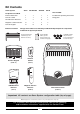
Kit Contents Alarm System SA1 E SA1 E PLUS SA1PF E SA2 E Also included: Components included: External Solar Siren 1 1 1 1 Installation & Operating Instructions Remote Control 1 1 1 1 Fixing pack PIR Movement Detectors 2 2 0 2 Magnetic Contact Detectors 0 2 4 2 Remote Keypad 0 0 0 1 Batteries included: The type and number of each battery included will depend upon the components included in the System purchased. 6V/1.
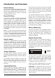
Introduction and Overview for more than 30 seconds or if the system is jammed for more than 3 periods of 10 seconds in a 5 minute period. (The Siren will emit a series of rapid beeps for 5 seconds as a pre-alarm warning 10 seconds before a full alarm occurs). System Arming The system has an Instant-Arm and Delay-Arm mode. If the system is armed in Instant-Arm mode then all detectors will immediately become fully armed. Any detector triggered while the system is armed will immediately sound an alarm.
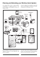
Planning and Extending your Wirefree Alarm System The example below shows a typical property incorporating the suggested positions for the Remote Keypad, PIR and Magnetic Detectors for optimum security. Use this as a guide for your installation in conjunction with the recommendations contained in this manual for planning your intruder alarm system.
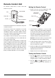
Remote Control Unit Setting the Remote Control The Remote Control Unit is used to Arm and Disarm the system. 1. Remove the front cover by undoing the small screw on the rear of the Remote Control. Transmit LED Arm Delay-Arm Disarm House Code Dip Switches Slide up to operate Jumper Link Personal Attack Battery Clip Battery The Remote will activate the Instant-Arm, Delay-Arm or Disarm functions. The Remote Control also incorporates a Personal Attack Switch (PAS).
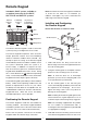
Remote Keypad Included in SA2 E system, available as an optional accessory for the SA1 E, SA1 E PLUS and SA1PF E systems. Transmit Indicator LED Low Battery Indicator LED Note: DO NOT fix the Remote Keypad to metalwork or locate the unit within 1m of metalwork (i.e. radiators, water pipes, etc) as this could affect the radio range of the Remote Keypad. Key Pressed Confirmation Indicator LED Installing and Configuring the Remote Keypad Ensure that the Siren is in Service mode.
5. There are two jumper links located above the battery compartment. Note: Use thumb and middle finger to hinge off the cover. The Remote Keypad has a back light illumination facility. It will illuminate for 5 seconds when opening the cover or pressing any key.
4. Refit the battery and test it by using the default User Access code of 1 2 3 4. 5. If the testing is ok, set the jumper link J2 as shown on Fig. 7a, which is what the Keypad is Testing the Remote Keypad 1. Press ? ? ? ? , User Access Code to arm the system set to normally, 2. 2 buttons together, 1 and Press and hold after approx. 2 seconds, an alarm will be initiated 3. Press Changing the User Access Code Default Code: 1 2 3 4 Press 2. Enter ? ? Press 1 , the Enter ? ? ? 1.
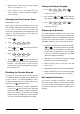
Passive Infra-Red (PIR) Movement Detectors PIR Detectors are designed to detect movement in a protected area by detecting changes in infra-red radiation levels caused, for example, when a person moves within or across the devices field of vision. If movement is detected an alarm signal will be triggered, (if the system is armed). The position of the PCB inside the PIR can be set to 5 different positions to adjust the range of the PIR Detector.
Note: DO NOT fix the PIR Detector to metalwork or locate the unit within 1m of metalwork (i.e. radiators, water pipes, etc) as this could affect the radio range of the device. To adjust the PCB position, simply slide it up or down ensuring that the location legs are aligned with the required position number marked on the board. 7. To refit the PIR Detector to the rear cover, offer it up to the rear cover and locate the clips in the top edge into the rear cover.
3. DIP 4 of SW3 is used to configure the PIR Detector for walk test mode, which allows the 5. Connect the PP3 alkaline battery to the battery clip. Note: When the 9V alkaline battery is connected, the LED behind the lens will flash for 2-3 minutes until the PIR has warmed-up and stabilized. The LED will then stop flashing and turn OFF. operation of the Detector to be checked during installation without triggering a Full Alarm.
Magnetic Contact Detectors The Magnetic contact comprises two parts; a Detector and a Magnet. They are designed to be fitted to doors or windows with the Magnet mounted on the opening part and the Detector mounted on the fixed frame. Opening the protected door/window will remove the magnetic field, trigger the Detector and generate an alarm condition, (if the system is armed). Installing and Configuring the Magnetic Contact Detector Ensure that the system is in Service Mode 1.
3. DIP switches 9 -11 must be set as follows. (Ensure back surfaces are flush) Detector Magnet 1. Remove the battery cover from the Detector. As the battery cover is removed the LED on the Detector will illuminate for approx. 1 second to indicate that the tamper switch has been activated. 7. Slide the batteries supplied into the holder, ensuring that the positive (+) side is uppermost on each battery as it is installed. 2. Open the door/window.
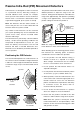
External Solar Siren Choosing a Location for the Solar Siren The Siren & Strobe unit should be fitted to the outside of the building in a position that is clearly visible and at a height which is relatively inaccessible to an intruder. Although the Siren & Strobe is designed to work on any aspect wall, you should refrain from fixing the unit on a North facing wall where possible. Shadows cast by neighbouring walls, trees and roof overhangs should also be avoided.
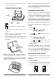
Front Cover Locating Tabs Solar Panel Receiver Aerial 7.5 Volt DC Charging Adaptor Input DIP Switch Cover Tamper Switch Beep Disable Link P2 P3 6 Volt 1.2Ah Rechargeable Battery Siren Disable Link P1 Jamming Detection Link 1 2 3 4 5 6 7 8 9 ON House Code DIP Switches 1-8 9 Volt PP3 Initial Power-Up Battery Printed Circuit Board Enclosure C.U. Alarm Duration DIP Switch 9 SIREN Main Configuration Switch (in C.U. Position) LED/Strobe PCB Siren C.U.
Once you have completed setting the Solar Siren, refit the DIP switch cover and replace the three cover fixing Siren Service Mode In order to remove the Siren from the wall to change the batteries, it is necessary to place the Siren into Service Mode to prevent the Tamper protection switch on the Siren operating and triggering an alarm. screws. Do not over tighten the screw as this could damage the thread. Initial Power-Up of the Solar Siren 1.
Testing the System Testing an Installed System If your system includes PIR Detectors: The system should be tested at regular intervals (at least every 3 months) to ensure that it is operating correctly. 8. Arm the system in Instant-Arm mode by pressing on the Remote Control. 1. Before commencing testing please ensure the following: The Siren will acknowledge the signal by beeping once, (unless Beep Disable has been selected). − The Siren is in Operating Mode and Disarmed 9.
Operating Instructions When leaving the premises, the system must be Armed. However, before doing so, check that all windows are closed and locked, all protected doors are closed and PIR Detectors are not obstructed. Ensure that pets are restricted to areas not protected by PIR Detectors. Arming the System ARM The system can be set in ARM mode using either the Remote Control or the Remote Keypad as follows: Remote Control: The system has 2 armed modes, Instant-Arm and Delay-Arm.
Enabling the Panic: Disarming the System The system can be disarmed using either the Remote Control or the Remote Keypad as follows: 1. Press 2. Enter Remote Control: 2 ? ? ? ? User Access Code Press the button. 3. Press The Siren will acknowledge the Disarm signal by beeping twice unless beep disable has been set. 2 , the LED will illuminate once and flash twice 4. Press 1 Remote Keypad: Press 5.
Remote Keypad: When the battery is low the ‘low-batt’ LED on the Remote Keypad will be illuminated. PIR Movement Detectors: Under low battery conditions the LED behind the detector lens will flash when movement is detected to indicate that the battery needs to be replaced. Under normal battery conditions the LED does not illuminate unless the PIR Detector is in Walk Test mode.
Maintenance Detectors, Remote Control and Remote Keypad Your alarm system requireds very little maintenance. However, a few simple tasks will ensure its continued reliability and operation. The detectors require very little maintenance. The batteries should be replaced once a year or when a low battery status is indicated. IMPORTANT: If, for any reason you have to completely power-down the Solar Siren (e.g.
Alarm Record You may make a note of your User Access Code and System House Code below. User Access Code System House Code ECE ON e.g. 1 2 3 4 5 6 7 = ON 8 Use the above diagram to record your House Code This information is confidential and should be kept in a safe location.
Troubleshooting Symptom / Recommendation Symptom / Recommendation c. Fit new initial power-up battery and re-power up Siren Siren immediately sounds when system armed 1. Siren tamper switch activated - adjust tamper plunger and ensure that switch fully closes when Siren is mounted. If the wall is excessively uneven, the Siren may need relocating to a more suitable position. 5. System locked - Reset system: a. Disconnect Siren rechargeable and initial power-up batteries. b.
Symptom / Recommendation Symptom / Recommendation PIR Movement Detector not detecting a person’s movement 6. If there is no additional wired Magnetic Contact connected ensure the jumper link is fitted. 1. Ensure the battery clip is securely connected. 7. If an additional wired Magnetic Contact is connected: 2. Ensure the ‘House Code’ is correctly set to the same code as all other system devices. a. Ensure the jumper link is removed. b. Check that both contacts are closed. 3.
Extending your Alarm System Your system may be extended to provide additional protection by adding further PIR Movement Detectors, Magnetic Contact Detectors and Remote Control Units.
Notes: 27
Component Specification External Solar Siren Wirefree Remote Keypad Remote Control (included in SA2 kit) 75 mm 315 mm 85 mm 39 mm ● ● ● ● ● ● ● ● ● ● RF operating frequency: 433MHz Sealed lead acid battery 6V/1.2Ah Solar Panel 7.